PN: L-MAM2-E-201
Moog Casella DM2020 Installation and Startup Guide
5.3.6.8 I/O Signal Connection
5.3.6.8 I/O Signal Connection
Connectors X5, X15, X6, X16
CAUTION
Analogue inputs are referred to 0 Volt analogue earth on pin 16; the 0 Volt digital earth is used for the power
supply for
the
digital outputs
Note on analogue inputs (X6-X16):
These are two programmable differential inputs for nominal analogue values. As the potential reference, connect pin
16 to the
torque limit for pins 3 and 4 when the drive is used in “analogue” mode
Maximum differential voltage: ±10 V
Reference earth: pin 16
Input resistance: 22 kOhm
Sampling rate: 32.5 usec
Resolution: 12 bit
Notes on digital inputs (X6-X16):
The programmable digital inputs on X6, DIG_INP 1 and 2, are also suitable for “latch” functions or for the quick
feedback (“capture”)
Notes on digital inputs (X5-X15):
configured
1. The RS232 serial interface with inputs and/or outputs
2. The simulated encoder
3. Digital I/O line drivers which may be programmed as inputs or outputs
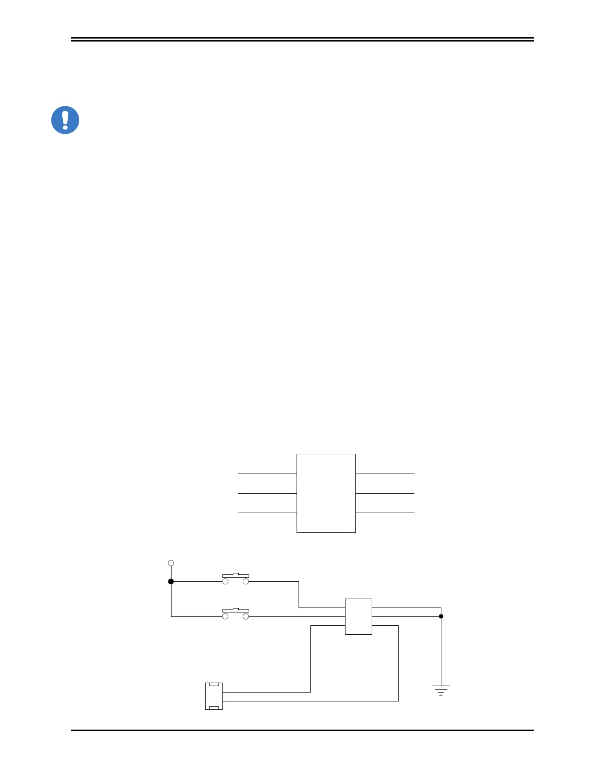
5.3.6.9 STO signals connection
Feedback CH 1
0 Volt CH 1
1
3
5
2
4
6
0 Volt CH 2
Feedback CH 2
+
24 Volt CH 1
+24 Volt CH 2
STO
X4 - X14
1
5
Monitoring inputs of the drive
Module or Safety PLC
Safety chain 2
Safety chain 1
+
24 Volt
0
V
olt
3
2
6
4
STO
X4 - X14
 Loading...
