PN: L-MAM2-E-201
Moog Casella DM2020 Installation and Startup Guide
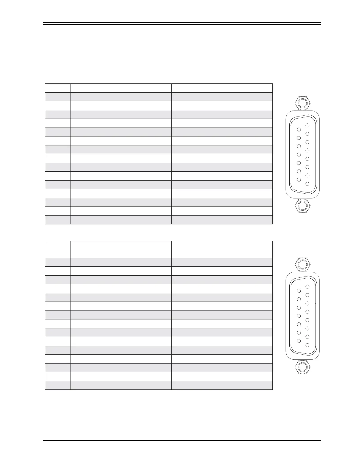
3.2.4.1 Connector Layout
PIN TTL incremental encoder function Sinusoidal encoder function
8
7
6
5
4
3
2
1
15
14
13
12
11
10
9
1 +5 V (max 100 mA) B
2 GND (encoder and PTC) 0 V supply
3 W- A
4 W+ Up supply
5 V+ Date+
6 V n.c.
7 A+ Term A
8 A- CLOCK +
9 C+ B+
10 C- 0 V Sense
11 U+ A+
12 U- Up Sense
13 B- Date
14 B+ Term B
15 PTC CLOCK
Use the X1(X11) connector to connect Hall sensors as indicated in the table below:
PIN Differential Hall sensor connector
Hall sensor connector
Single-ended
8
7
6
5
4
3
2
1
15
14
13
12
11
10
9
1 +5 Volt +5 Volt
2 0 V supply 0 V supply
3 W- n.c.
4 W+ W+
5 V+ V+
6 V n.c.
7 n.c. n.c.
8 n.c. n.c.
9 n.c. n.c.
10 n.c. n.c.
11 U+ U+
12 U- n.c.
13 n.c. n.c.
14 n.c. n.c.
15 PTC-NTC-Mot PTC-NTC-Mot
(*) The use of the X1 (X11) connector is optional.
3.3 Layout of connectors and other interfaces on the axis module
The tables of connector pins relative to the axis module are shown below in the various possible coni gurations.
X1 (X11) connector (*)
 Loading...
