PN: L-MAM2-E-201
Moog Casella DM2020 Installation and Startup Guide
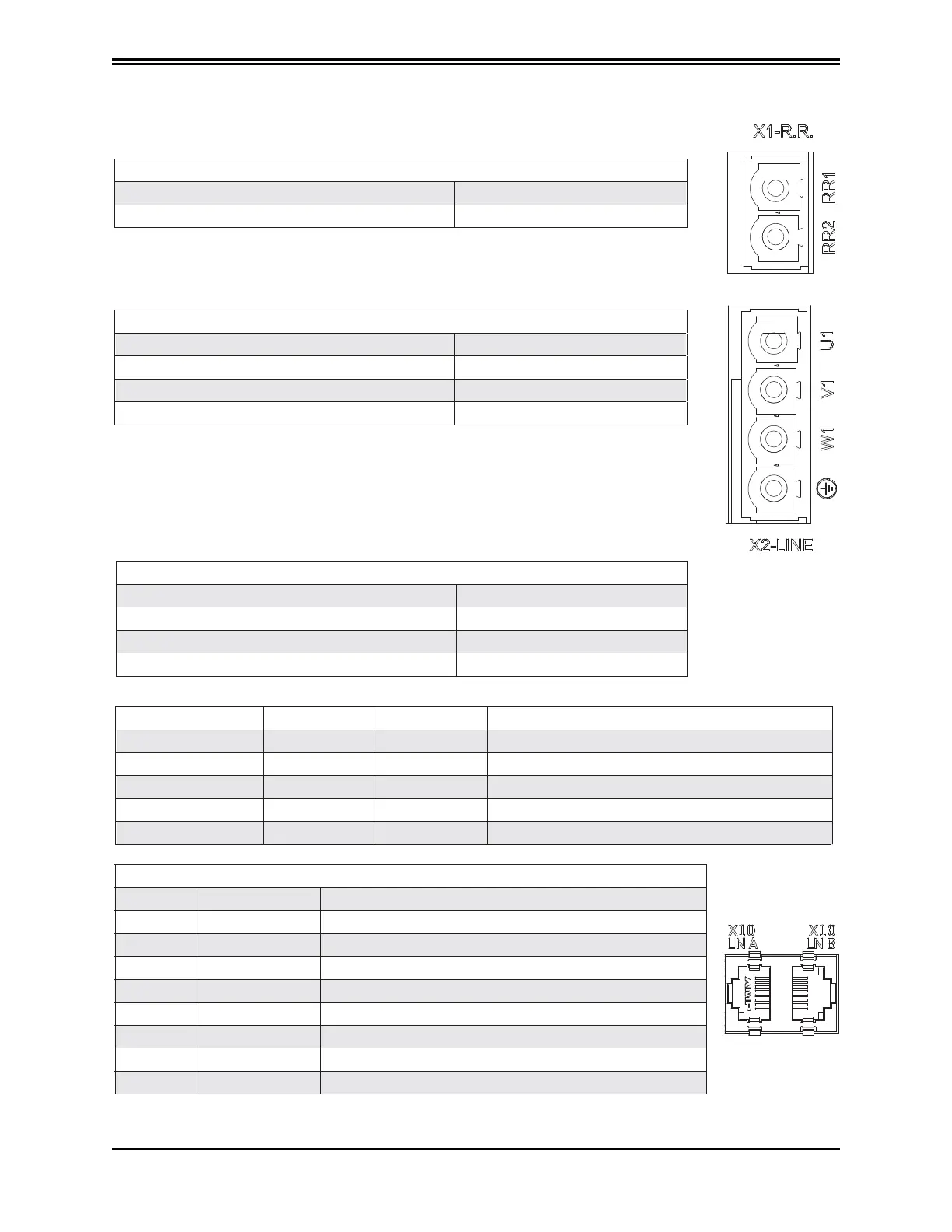
3.2.3.1 Connector Layout
X1: brake resistor
1 +RR1
2 -RR2
X2: mains
1 U1
2 V1
3 W1
4 Earth
BUSBAR connection
1 +24 V
2 0 V DC
3 +DC BUS
4 -DC BUS
YELLOW LED GREEN LED RED LED Status
Off Off Off Power supply off or failed
Off On, fixed light Off 24 Volt applied
Flashing Flashing Off Three-phase power supply present, BUS charging
On, fixed light Flashing Off BUS stable, axes ready to be enabled
Off Off On, fixed light Power supply fault
X10 LN A CAN connector (according to CIA 402 CAN on RJ45 connector)
Pin Designation Function
1 Can_H CAN line positive terminal
2 Can L CAN line negative terminal
3 0 V_ Ca n CAN line 0 logic
4 Aux_Ps_Fault_neg Signal (active low) of power supply status
5 Addr_ sx _dx Address for internal communications
6 Ps_out Power supply command output
7 nc
8 +5V_Can CAN line power supply (supplied by power supply)
3.2.4.1 Connector layout
The tables below give details of connectors and the meaning of signalling LEDs
 Loading...
