PN: L-MAM2-E-201
Moog Casella DM2020 Installation and Startup Guide
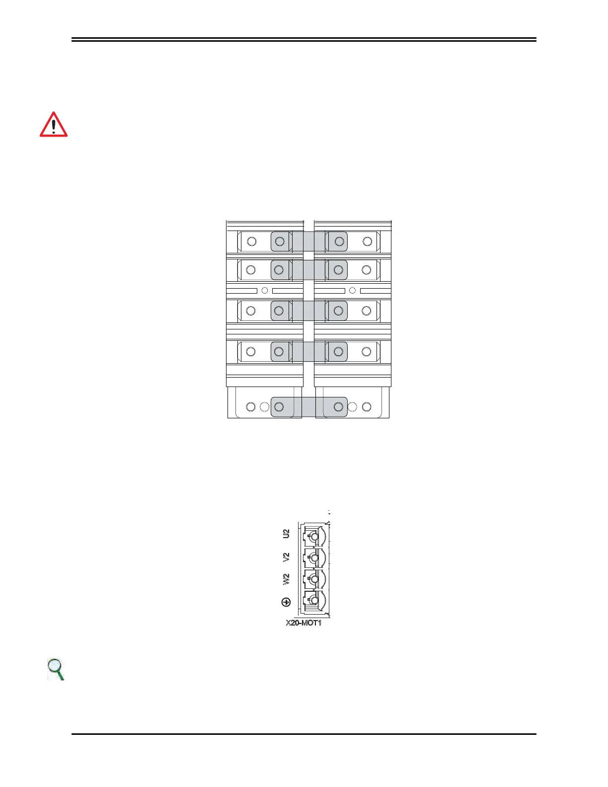
5.3.6.3 BUSBAR Connection
+24 Volt
0 Volt
+ AT
- AT
GND (PE)
Connecting the power (+/- AT) and auxiliary voltage via BUSBAR
5.3.6.3 BUSBAR connection
The +DC bus and -DC bus terminals of the power supply and axis modules must be connected in
parallel. In this way, the power from the power supply and power from regeneration are divided
between all axis modules. Only the BUSBARs provided with the drive must be used for connections.
WARNING
The user is responsible for the physical protection of the BUSBARs and other safety devices
intended to prevent harm to persons: For this purpose, the front cover or two side covers provided
with the drive must be used (on the two modules at each side of the system).
AVERTISSEMENT
L'utilisateur est responsable de la protection physique des BUSBAR et autres dispositifs de sécurité
destinés à prévenir les dommages aux personnes: A cet effet, le capot avant ou le deux couvercles
latéraux fournis doivent être utilisés (sur les deux modules de chaque côté)
5.3.6.4. Auxiliary voltage and signal connection
The 24 V DC auxiliary voltage must be provided from an external source to the +24 V and 0 V terminals
on the front panel. The power supply is equipped with a CAN (X10) connector which provides direct
power to the drives' CAN line; the pin is the same as that one the axis modules. See section “2.2.2.
Connectors and LEDs”.
Connector X20 (X21)
INFORMATION
If power cables for the motor are longer than 50 m and have a capacity above 150 pF/m, dispersion
currents could cause erroneous alarms with the power sections of the drives. This can be remedied using
an inductor in series for the power cable, positioned as close as possible to the drive. Please contact
the Applications Department for any necessary inductor sizing
 Loading...
