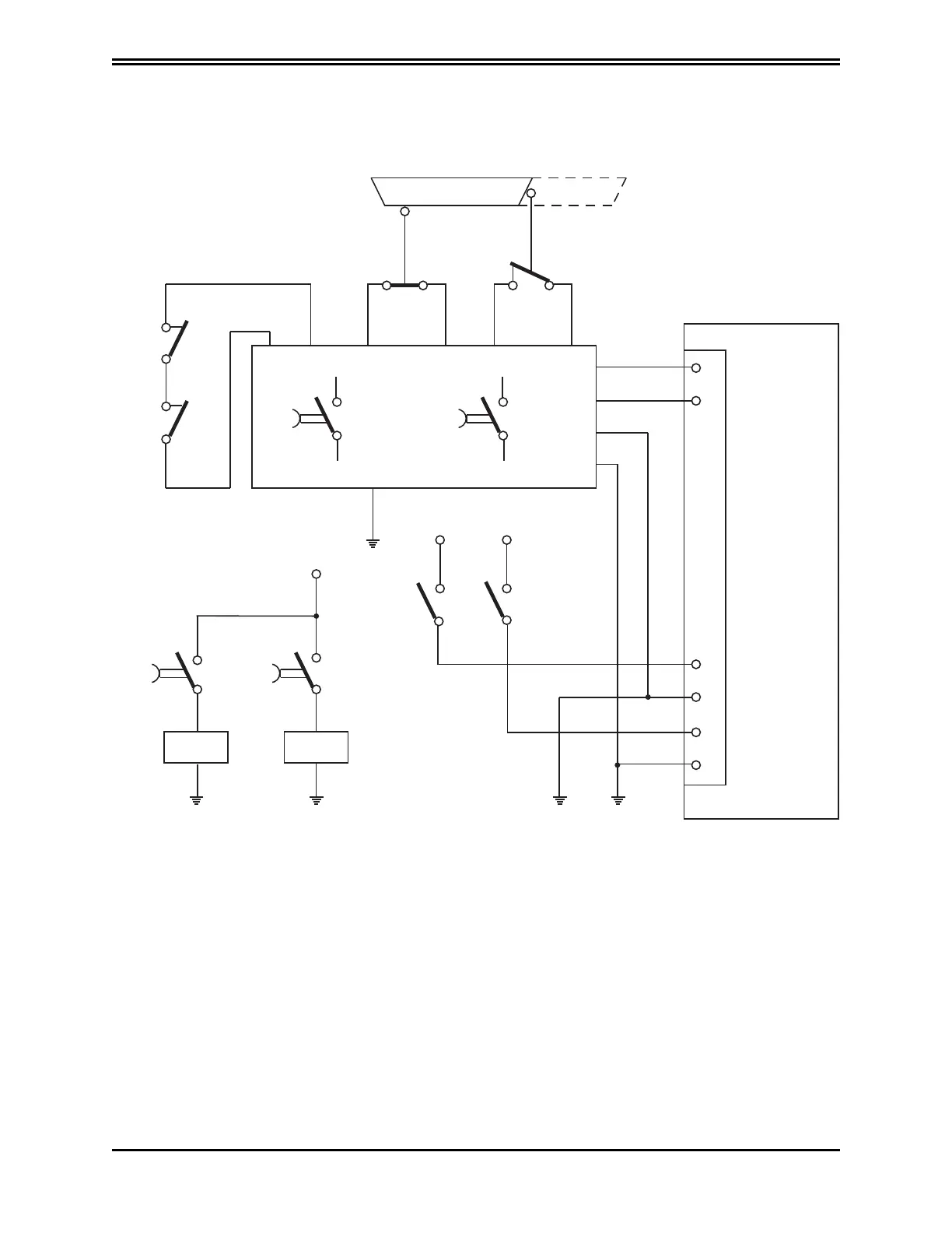
10.7 Example Application
The following figure illustrates an example circuit for Safe Torque Off after a controlled stop.
A1
33
34
37
38
- SW1 - SW2
CLOSED OPEN
DRIVE
- Q1
- Q2
SAFETY PLC
6
5
1
2
3
4
Ch 1
Ch 2
Ch 1 Verification
Ch 2 Verification
- Q1 - Q2
- Q1 - Q2
- A1 - A1
+ 24 V + 24 V
JRIC1
+ 24 V
33
34
37
38
Example
of
Safe
Torque
Off
After
a
Controlled
Stop
10.7.1 Description
Two redundant channels are used. The switches SW1 and SW2 are connected to an A1 safety PLC that
controls two contactors, Q1 and Q2, with associated contacts. The NO contacts of Q1 and Q2 control
the two input channels of the DM2020 safety for the shutdown of the motor power connections. The
NC contacts of Q1 and Q2 are used in series to control the A1 safety PLC in the event of welding of a
NO contact. The two output safety channels of the DM2020 are connected to an A1 safety PLC to
allow the diagnostic coverage of the DM2020 subsystem.
PN: L-MAM2-E-201
Moog Casella DM2020 Installation and Startup Guide
10.7 Example Application
 Loading...
