PN: L-MAM2-E-201
Moog Casella DM2020 Installation and Startup Guide
3.2.3.3 Brake resistor
3.2.6 Brake resistor
When the motor decelerates, braking resistance converts energy into heat.
There are two different brake resistors for the L50 power supply:
Code Power (W) Ohm Notes
Standard 370 15 Supplied
AR5974 500 16 Available as an option to be ordered separately
The braking resistor is not provided for the L150 power supply. The recommended resistor is 4.7 ohms/1000 watts
(to be ordered separately using code AR5988).
INFORMATION
If the dissipated power exceeds 1000 W, contact the Applications Service at Moog-Casella for component
sizing
CAUTION
For the L50 model, the braking resistor must always be connected as it also features a soft-start
function. In the absence of this, the system will not start up; moreover, it will not be possible to stop the
rotating motors in a controlled manner.
ATTENTION
Pour le modèle L50, la résistance de freinage doit toujours être raccordée car il dispose également
d'une fonction de démarrage progressif. A défaut de cela, le système ne démarrera pas; en outre, il ne
sera pas possible d'arrêter les moteurs rotatifs d'une manière contrôlée.
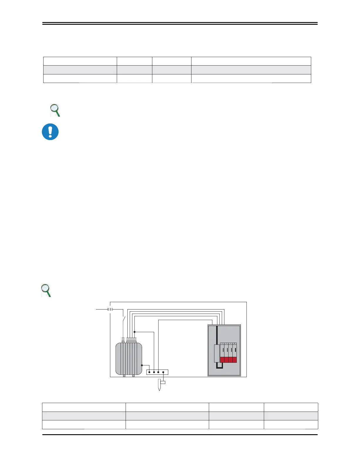
3.2.7 Line inductors
For normal operation, inductors do not have to be used at the power supply input.
However, if using a low-inductance network (below 100 uH, it is advisable to it a line inductor to the network in
order to protect the power supply.
Systems with a very low line inductance produce dV/dt values above 1000 V/uS of the three-phase input
voltage applied to the drive. This is a limit value for thyristors, which IN THESE PARTICULAR CONDITIONS may
become conductive, even without controlled triggering by the internal circuit.
Specifically, if switched on early, they may cause the fuses in the soft-start circuit to break (the soft-start circuit is
designed to limit starting current caused by the DC BUS capacitors preventing uncontrolled currents).
To define an approximate value for line inductance, the cable length between the three-phase input of the
drive and MV/LV transformer cabin must be considered, using 0.6 uH/m as a typical inductance value per
metre of wiring, and summing the inductance of the transformer cabin.
To limit possible dV/dt, the effect of limiting the value induced by the input EMC filter should also be considered,
checking the filter inductance value.
INFORMATION
The inductor must be fitted between the transformer of the cab and the drive
TOTAL LINE INDUCTANCE 100 uH
DM2020_D_005
Diagram of a three-phase input inductor connection
Power supply size Inductance value Current Frequency
Type L50 0.1 mH Inom. 60 A 50/60 Hz
Type L150 0.1 mH Inom. 130 A 50/60 Hz
 Loading...
