PN: L-MAM2-E-201
Moog Casella DM2020 Installation and Startup Guide
3.2.3.2 Filters
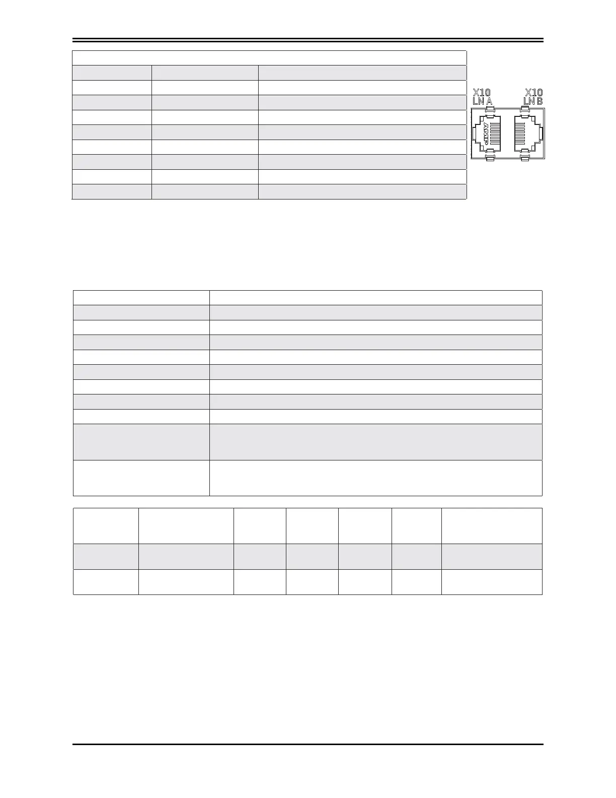
X10 LN B CAN connector (according to CIA 402 CAN on RJ45 connector)
Pin Designation Function
1 Can_H CAN line positive terminal
2 Can L CAN line negative terminal
3 0V_ Ca n CAN line 0 logic
4 Aux_Ps_Fault_neg Signal (active low) of power supply status
5 Add r_ sx _d x Address for internal communications
6 Ps_out Power supply command output
7 nc
8 +5V_Can CAN line power supply (supplied by power supply)
3.2.5 Filters
If the motor power cables are shorter than 50 m, an EMC filter (code AT6013/AT6014 or equivalent
can be positioned between the network and the drive.
If cables are longer than 50 m, we recommend contacting Moog-Casella's Applications department.
Filter code AT6013 (power supply M) / AT6014 (power supply L)
Rated voltage 3 x (400/480 V), 50/60 Hz, at 50 °C
Overload 1.5x per 60 s, repeatable every 60 min.
Ambient temperature From -25 °C to +100 °C, with current reduction starting from 60 °C (1.3%/°C)
Assembly height 1000 m, with current reduction of up to 4000 m (6%/1000 m)
Relative air humidity 15 - 85% (condensate not permitted)
Storage temperature From -25 °C to +70 °C
IP protection rating IP20
Acceptance test Complies with EC
Non-industrial environment -
EN61800-3
complies with radio shielding
Cable length permitted between the drive and motor up to 50 m
Industrial environment -
EN61800-3
complies with radio shielding
Cable length permitted between the drive and motor up to 100 m
Code
Suitable for
power supply
Rated
current
[A]
Total
current
loss [W]
Current
on contact
[mA]
Weight
[kg]
Connection [mm
2
]
AT6049 L50 55 29.3 6.6 2.5
Up to 16 mm
2
AT6054 L150 137 42.2 7.1 5
From 10 to 50 mm
2
Main electrical characteristics of filters
For special installation requirements, alternative versions of the filters are also available. Please
contact Moog for further information.
 Loading...
