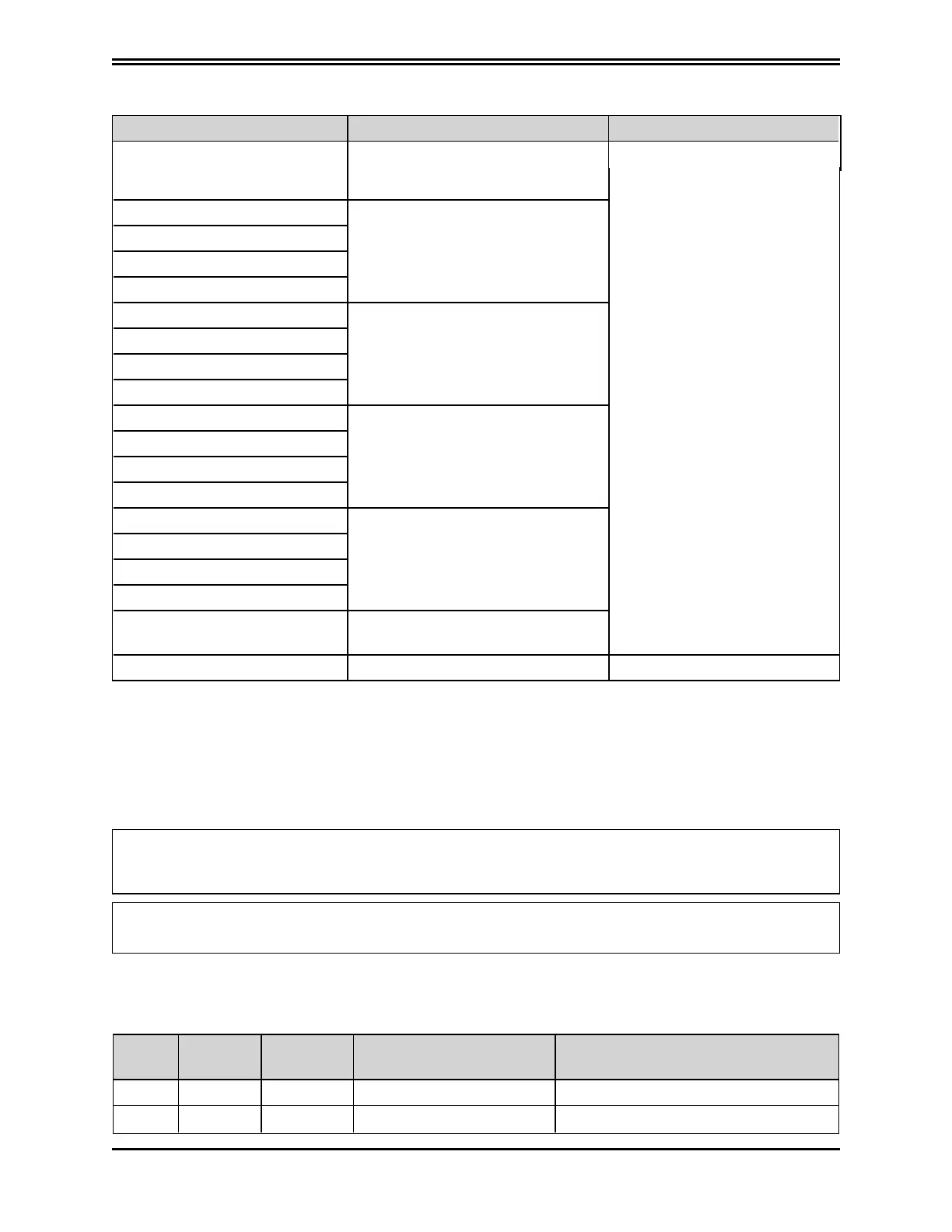
after the timeout
Check wiring configuration
of the drive communication
and/or the CAN master
CAN_rpdo0_time_out PDO data not received or received
after the timeout
CAN_rpdo1_time_out
CAN_rpdo2_time_out
CAN_rpdo3_time_out
CAN_rpdo0_data PDO data received incorrectly
CAN_rpdo1_data
CAN_rpdo2_data
CAN_rpdo3_data
CAN_tpdo0_time_out PDO data not received or received
after the timeout
CAN_tpdo1_time_out
CAN_tpdo2_time_out
CAN_tpdo3_time_out
CAN_tpdo0_data Data not transmitted
CAN_tpdo1_data
CAN_tpdo2_data
CAN_tpdo3_data
CAN_sync_consumer_time_out Sync not received or received after
the time out
CAN_life_guard_error Error on the life guarding protocol Check the configuration
9.3 Alarm Display in Analog Operating Mode
If the drive is operating in "Analog" mode (Mode and Commands / Mode Operation: Analog), the
LEDdisplay on the front panel indicates the presence of an alarm and an additional error index,
consisting of 2 numerical digits. This allows the operator to identify the cause of the error present
without a PC. For example, in the case of an EEPROM fault (Fault Index 13), it will display error F-1-3.
If the drive is used in fieldbus mode (EtherCAT/CAN), the display will show a fixed F, the error
code will be transmitted through an EMERGENCY message (according to the CANopen standard)
using ErrorCode and ErrorRegister.
If CANopen is used, an emergency message is transmitted according to the CANopen Emergency
protocol using the Error Code and the Error Register (so there is no "F" character).
The following table lists the set of available faults and their descriptions. Note that the hard faults
(the first 8 bold rows) are not configurable; the reaction is always "Disable". For details on configuring
fault reactions, see
System Configuration
.
Fault
Index
Error
Code
Error
Register
Fault Description
1 0x2344 0x04 short_circuit_phase_U_low IGBT fault, phase U, low arm
2 0x2345 0x04 short_circuit_phase_U_hi IGBT fault, phase U, high arm
PN: L-MAM2-E-201
Moog Casella DM2020 Installation and Startup Guide
9.3 Alarm Display in Analog Operating Mode
9.2.12 CAN Bus Alarms
Fault Cause Action
CAN_communication_fault PDO data not received or received
 Loading...
