MOOR INSTRUMENTS moorLDI2 RESEARCH USER MANUAL
6
being scanned such that if the laser light beam is missing the body it is stopped by the screen.
A dark cloth screen is recommended.
If a suitable screen is not available the body should be scanned with a wall as background.
During a measurement no personnel other than the person being scanned should be present in
the area between the scanner and the screen or wall.
c. Care should be taken to prevent unintentional specular reflections. Any metallic or other
highly reflective surfaces must be removed from the area to be scanned or covered with
material to produce diffuse reflection, e.g. removal or taping over of rings etc.
1.2.2.6 Key Control
The moorLDI2-IR has a key control that prevents access to the Near Infrared laser radiation (see
Section 2 of this manual, Figure 2G). When the equipment is to be left unattended the key control
should be set to the OFF position and the key removed to prevent unauthorised operation.
1.2.2.7 Remote Interlock Connector
The moorLDI2-IR scanner is provided with a remote interlock connector which can be connected to
an emergency master disconnect interlock or to room, door or fixture interlocks if the Laser Safety
Officer considers it necessary. The person in charge may temporarily override the remote interlock
using the shorting plug supplied if it is clearly evident that there is no optical radiation hazard at the
time and point of entry.
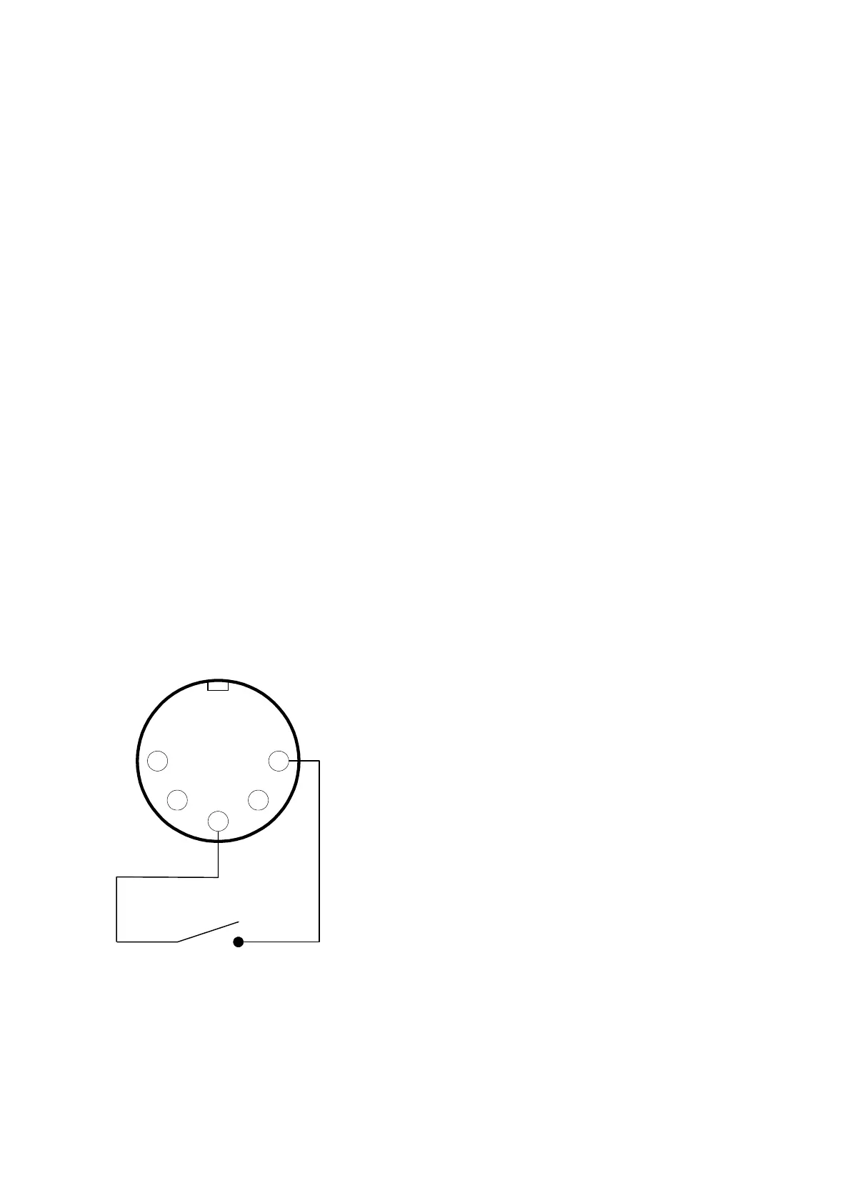
A non-wired plug is supplied with the system and may be wired to the interlock device(s) as shown
below. When the interlock circuit is open, the infra-red laser is disabled.
5
3
1
24
The interlock device should be wired to pins 1 and
3. The plug is shown as viewed from the inside
(i.e. as seen when soldering connections).
Follow the instructions supplied with the connector.
Only insert contacts into the positions shown, any
unused contacts may be discarded.
Interlock device,
e.g. door switch, emergency
stop switch etc.