MOOR INSTRUMENTS moorLDI2 RESEARCH USER MANUAL
141
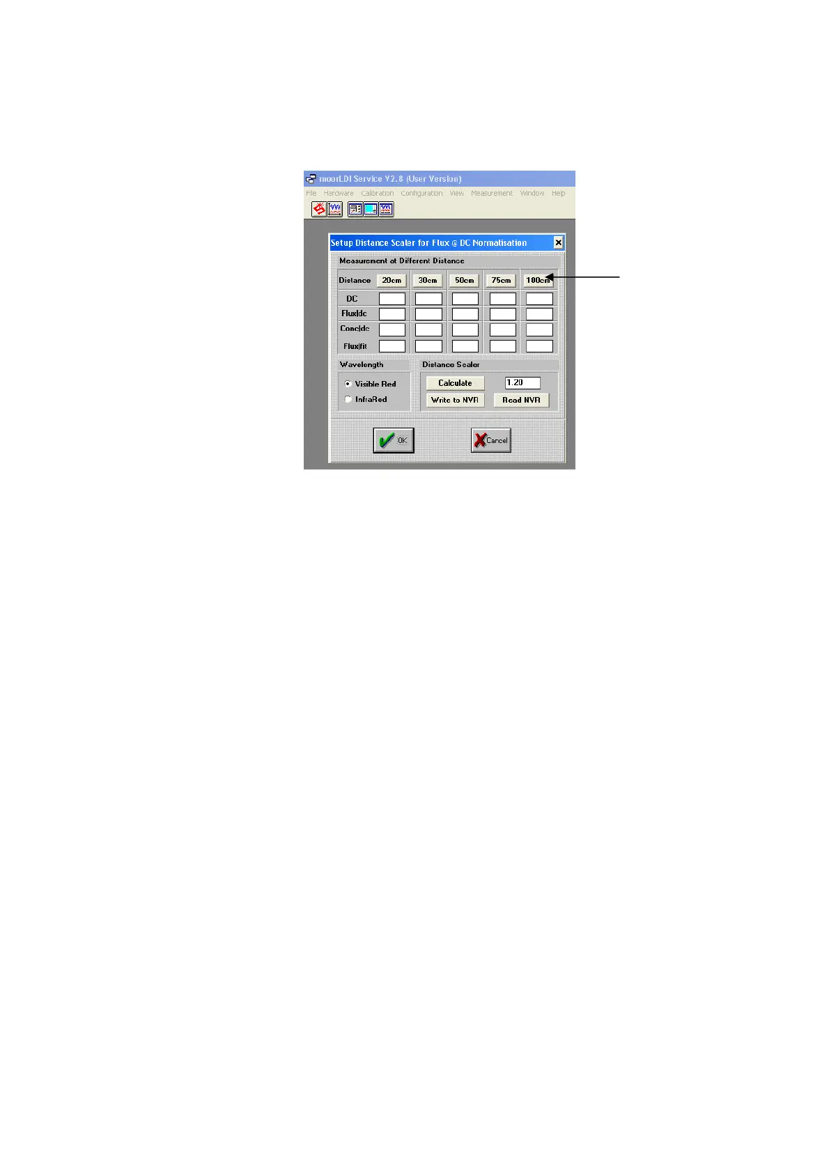
The following screen will appear:
3.5 Check the background lighting: this is an important step. The background lighting must be
sufficiently low prior to calculation of the distance scaler.
a) Set up the LDI in exactly the same way as for calibration, observing the same precautions.
b) Remove the calibration block. Place a piece of black cloth 100cm from the front of the LDI.
c) Ensure the laser beam is aimed at the black cloth.
d) Ensure there is no reflection into the scan head i.e. from a white/light coloured wall or
surface.
e) Click on the 100cm measurement button.
f) If the DC reading is HIGHER than five; reduce the lighting and repeat steps a-e.
g) If the DC reading is below five; continue with the distance scaler measurements (see 3.6).
3.6 Click 30cm button to perform the flux measurement at 30cm.
3.7 Move the front face of the calibration block to 48cm from the LDI front panel. Check the laser is still
aimed at the centre of the calibration bottle. Click the 50cm button to perform a flux measurement.
3.8 Move the front face of the calibration block to 73cm from the LDI front panel. Check the laser is still
aimed at the centre of the calibration bottle. Click the 75cm button to perform a flux measurement.
3.9 Move the front face of the calibration block to 98cm from the LDI front panel. Check the laser is still
aimed at the centre of the calibration bottle. Click the 100cm button to perform a flux measurement.
3.10 After all four measurements have been performed, click ‘Calculate’. This function calculates the
‘best fit’ Distance scaling factor for your system.
100cm
Measurement
Button