97
参数设定
PARAMETER SETTING
2 注意 2 NOTE
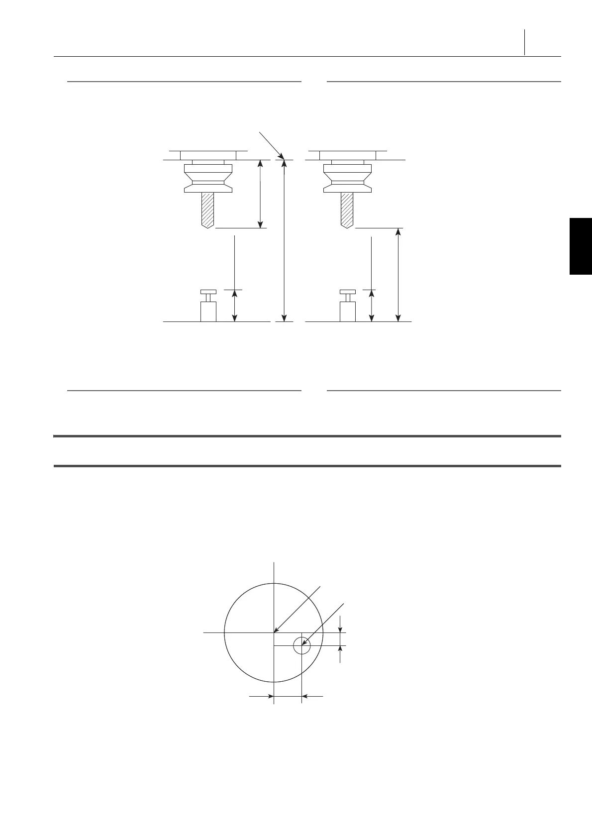
类型 2 的偏移量设置范围从 −9999.999 至 9999.999。 The setting range for the offset amount for type 2 is from
−9999.999 to 9999.999.
4) 将光标移动至‘B:底部水平量 ’,然后移动至‘Z:参考量具高
度 ’。
4) Move the cursor to ‘ B: BOTTOM LEVEL AMOUNT ’ and
then ‘ Z: REF. GAGE HEIGHT ’.
2 注意 2 NOTE
底线值仅适用于类型 1。 BOTTOM LEVEL AMOUNT is only for Type 1.
5) 输入各值。 5) Input each value.
11-2 ‘ 中心位置补偿 ’屏幕设定
‘ CENTER POSITION OFFSET ’ Screen Setting
传感器触针的中心不在实际的中心,有一微小的偏差。在预先
设置参数前,测量该值并将其输入。为了保持很高的对中精度
,定期测量此误差,当触针更换或者受到冲击时也应测量。若
更换触针或误撞了触针,务必测量和设置误差值。
The center of the sensor stylus is not at the true center; there is
a slight error. Measure this value and enter it as the setup
parameter beforehand. To maintain high centering accuracy,
measure this error regularly, and when the stylus is replaced or
subjected to impact. If the stylus is replaced or a shock is
applied to the stylus mistakenly, the error amount must always
be measured and set.
1) 将环规或带镗孔的试样放置在工作台上。 1) Place the ring gage or the test piece with the bored hole on
the table.
2) 使用杠杆百分表找出中心。 2) Find the center using a lever type dial test indicators.
3) 将主轴放置到所找到的中心。 3) Position the spindle at the found center.
<Type 1>
<Type 2>
Spindle Gage Line
Tool Length
Offset Data
Bottom Line
Height of Reference Block
Table Upper Surface
Tool Length
Offset Data
<类型1>
<类型2>
主轴基准线
刀具长度偏移数据
底线
基准块的高度
工作台上表面
刀具长度偏移数据
Spindle Center
Stylus Center
ΔY Direction
ΔX Direction
主轴中心
触针中心
ΔY方向
ΔX方向