9 Principles of Operation
9.1 Introduction
The 1936/2936 Series Power Meters electronics adapt to a number of signal
measurement tasks: DC current or voltage, AC peak-to-peak current or pulse
voltage, or integrated DC current or voltage signals. This versatility is
required to handle the various signals that Newport’s Low Power, High-
Power, Energy and other detector families generate. These detector families
are based on semiconductor, thermopile, pyroelectric as well as radiometric,
photometric and other detectors. The detector data is introduced to the
1936/2936 Series by way of a calibration module specific to the detector in
use. At power up (and RESET), the 1936/2936 downloads information about
the detector from the calibration module or the detector internal memory.
Based on the calibration module preprogrammed data, the meter learns the
set of operating states available to the detector. The user then selects among
the available operating states when using the meter. Front panel control and
the operating states of the Model 1936/2936 Series are discussed in
Sections 3.
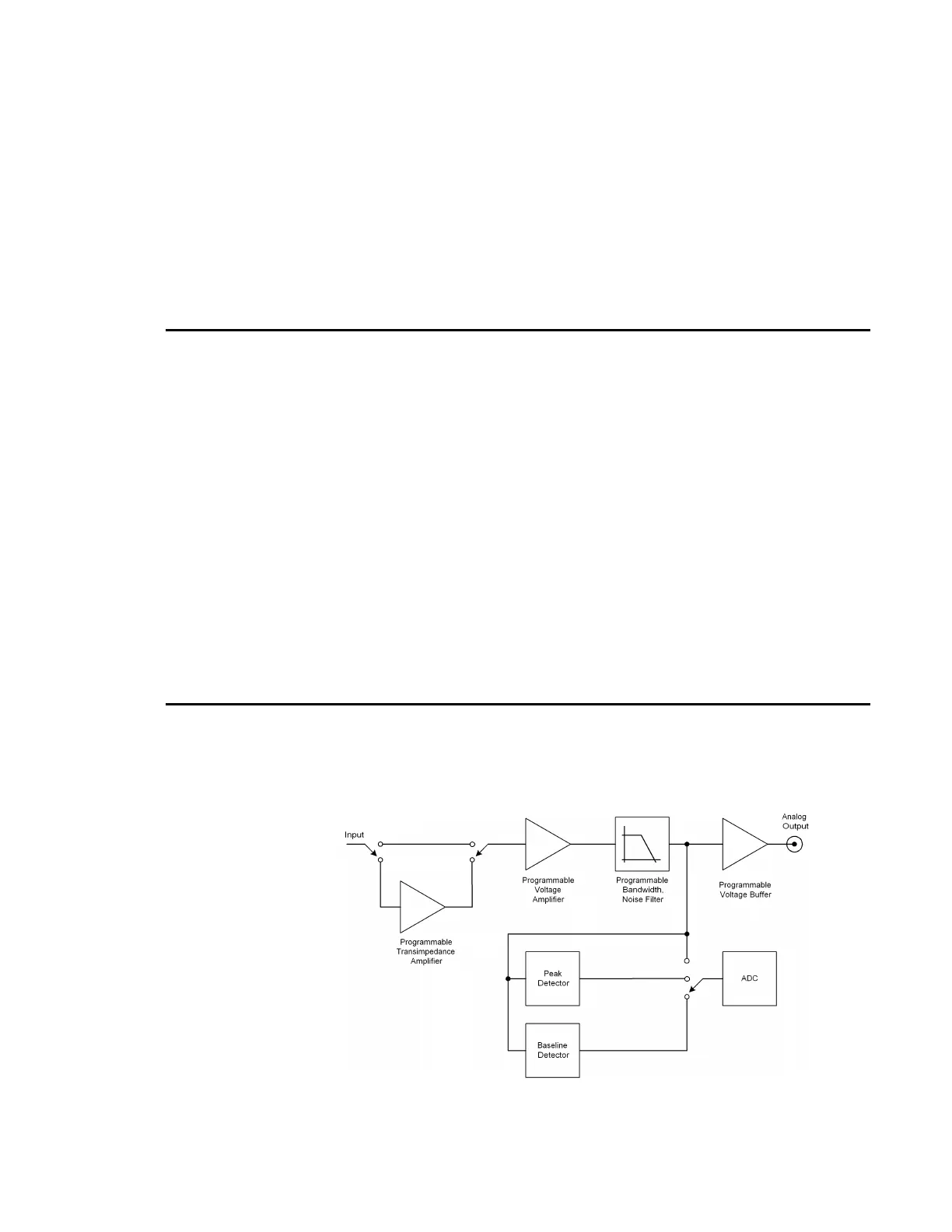
9.2 Analog Signal Flow
The detector signals can follow many different paths through the 1936/2936
Series input amplifier chain. A block diagram of analog signal flow is shown
in Figure 22. The actual flow path depends upon the detector type and the
mode of measurement.
Figure 64 Model 1936/2936 Series Analog Signal Flow Diagram

 Loading...


