System Overview 37
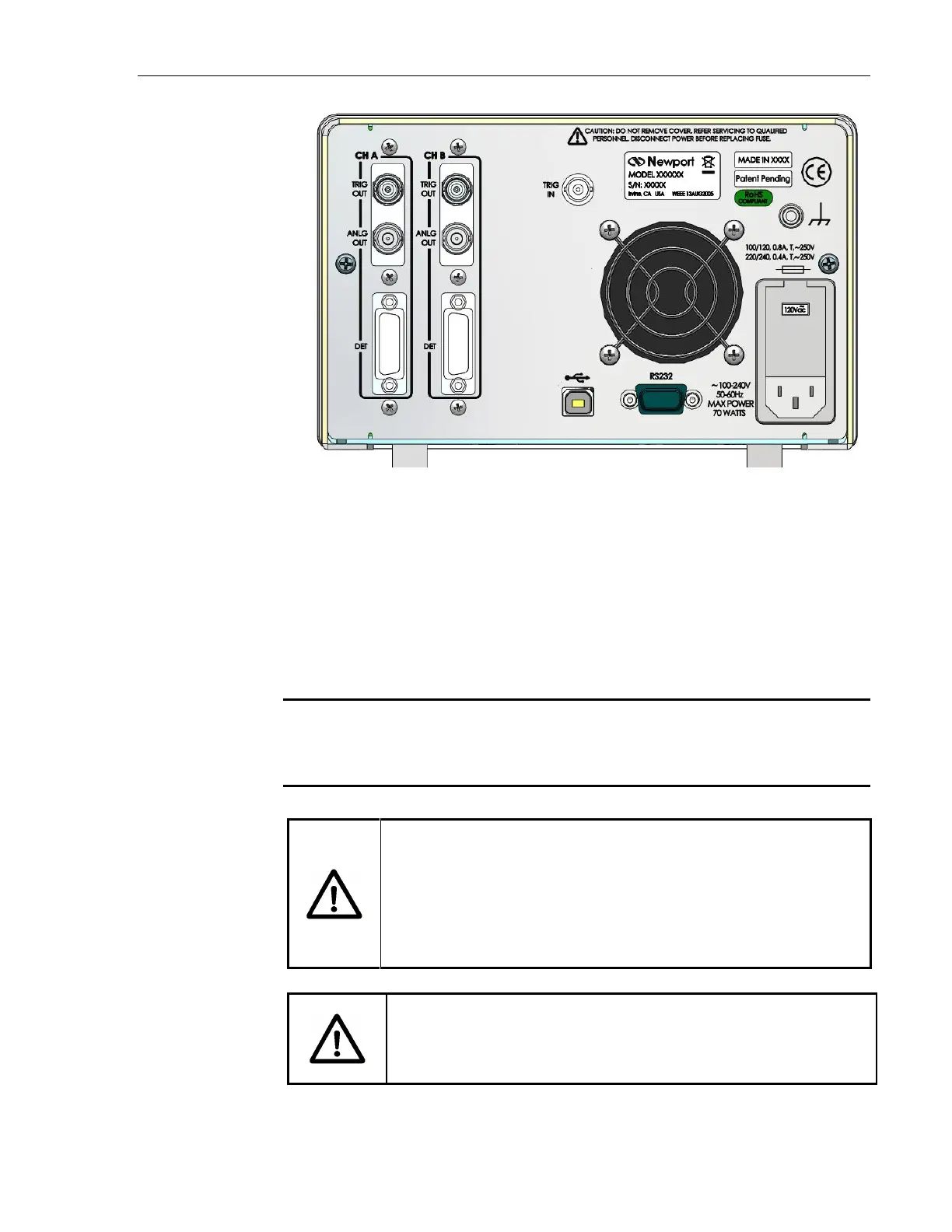
Figure 17 2936-R Rear Panel Layout
The rear panel also has an AC input power connector (IPC) with a standard
three-prong socket and voltage setting switch.
The unit can also be grounded with a circular metal shell connector.
Markings on the rear panel identify electrical requirements for the Optical
Power Meter and potential hazards associated with using it.
NOTE
For the listed optional connectors some units may have a cover in place of the non-
functional connector.
CAUTION
Change the voltage settings switch to the proper AC voltage
supply. Do not operate with a line voltage that is not within
10% of the line setting. Too low of an input voltage may cause
excessive ripple on the DC supplies. Too high of an input
voltage will cause excessive heating.
CAUTION
There are no user-serviceable parts inside the power meter.
Work performed inside the power meter by persons not
authorized by Newport may void the warranty.
 Loading...


