36 System Overview
Output Connectors
Power meters in the 1936/2936-R series support one analog output for each
channel. Analog output enables direct monitoring of a detector through an
oscilloscope or voltmeter.
On the rear panel there are also trigger outputs, one for each channel. The
user can use these outputs to synchronize external equipment with events
related to the power meter measurements.
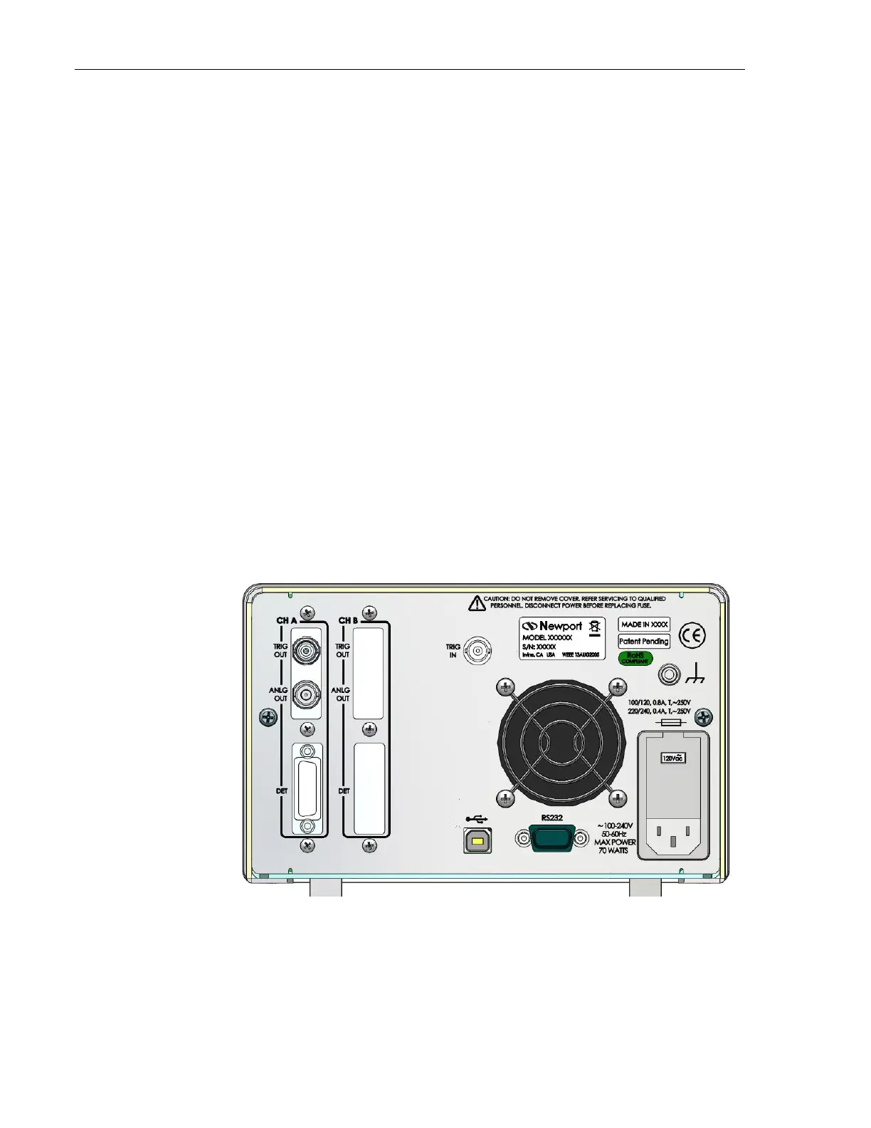
3.3.2 Panel Layout
The rear panel is a brushed aluminum plate with input and output connectors
for the following cable types (Figure 16):
15-Pin D-Sub Optical Detector Input, Channel A (1936-R/2936-R)
BNC Analog Output, Channel A (1936-R/2936-R)
BNC Trigger Output, Channel A (1936-R/2936-R)
15-Pin D-Sub Optical Detector Input, Channel B (2936-R)
BNC Analog Output, Channel B (2936-R)
BNC Trigger Output, Channel B (2936-R)
BNC Trigger Input
USB (Universal Serial Bus) Device
9-Pin D-Sub RS-232
Figure 16 1936-R Rear Panel Layout
 Loading...


