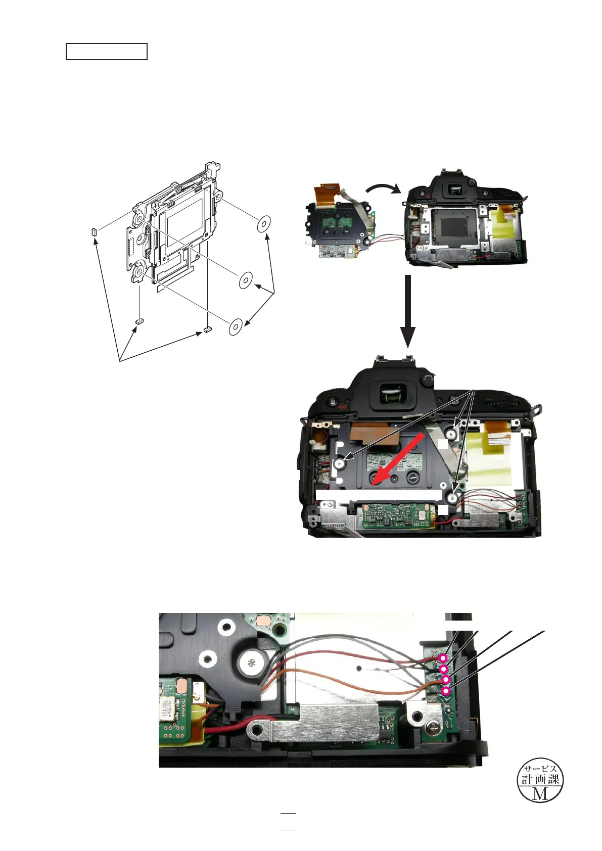
・Position the image sensor unit (#B1051) in the direction of the red arrow, and mount them. Then, tighten the threeimage sensor unit (#B1051) in the direction of the red arrow, and mount them. Then, tighten the three
screws (#680) in numeric order.
Caution: Some bodies have lumirror sheets (#62) and washers (#63) already attached. (ref. Page A46)(#62) and washers (#63) already attached. (ref. Page A46) (#63) already attached. (ref. Page A46)(#63) already attached. (ref. Page A46)46)
・Solder the wires (Red/Black/Orange/Gray).Solder the wires (Red/Black/Orange/Gray).
①
②
③
Image sensor unit (#B1051)
Screw
×3
(#680)
Wire
×4
(Red/Black/Orange/Gray)
Image sensor unit
(#62)
(#63)
Direction for positioning
VBA23001-R.3762.A
- A76 ・ D90 -
A73
Changed page △×1
△(Revision)
October. 2. 2008
 Loading...