XZAC4219-05 Service Manual
7-25
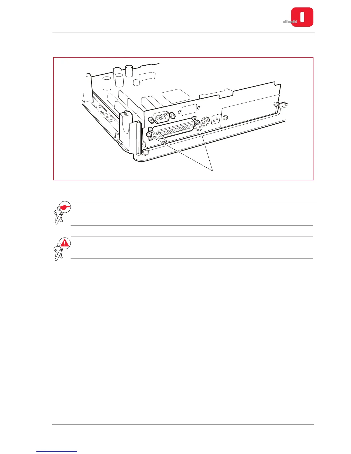
7. Back off the two screws (1) of the Centronics interface connector and extract the motherboard from the
baseplate of the printer.
Figure 7 - 33 Parallel interface connection screws
NOTE: when replacing the board, update the firmware with the latest release, configure the parameters
(see the section “CONFIGURING THE OPERATION PARAMETERS” on page 4 - 1) and calibrate
the photosensors (see the section “CALIBRATING THE PHOTOSENSORS” on page 4 - 18).
WARNING: when reassembling the motherboard, tighten the screws of the earth connections for
both the board and the power unit, ensuring a perfect grounding.