4 - 21
4 Setting the Controller
Vision System FH/FHV/FZ5 Series User’s Manual (Z365)
4-4 Setting Operation Mode [Startup Settings]
4
4-4-1 Setting the Operation Mode
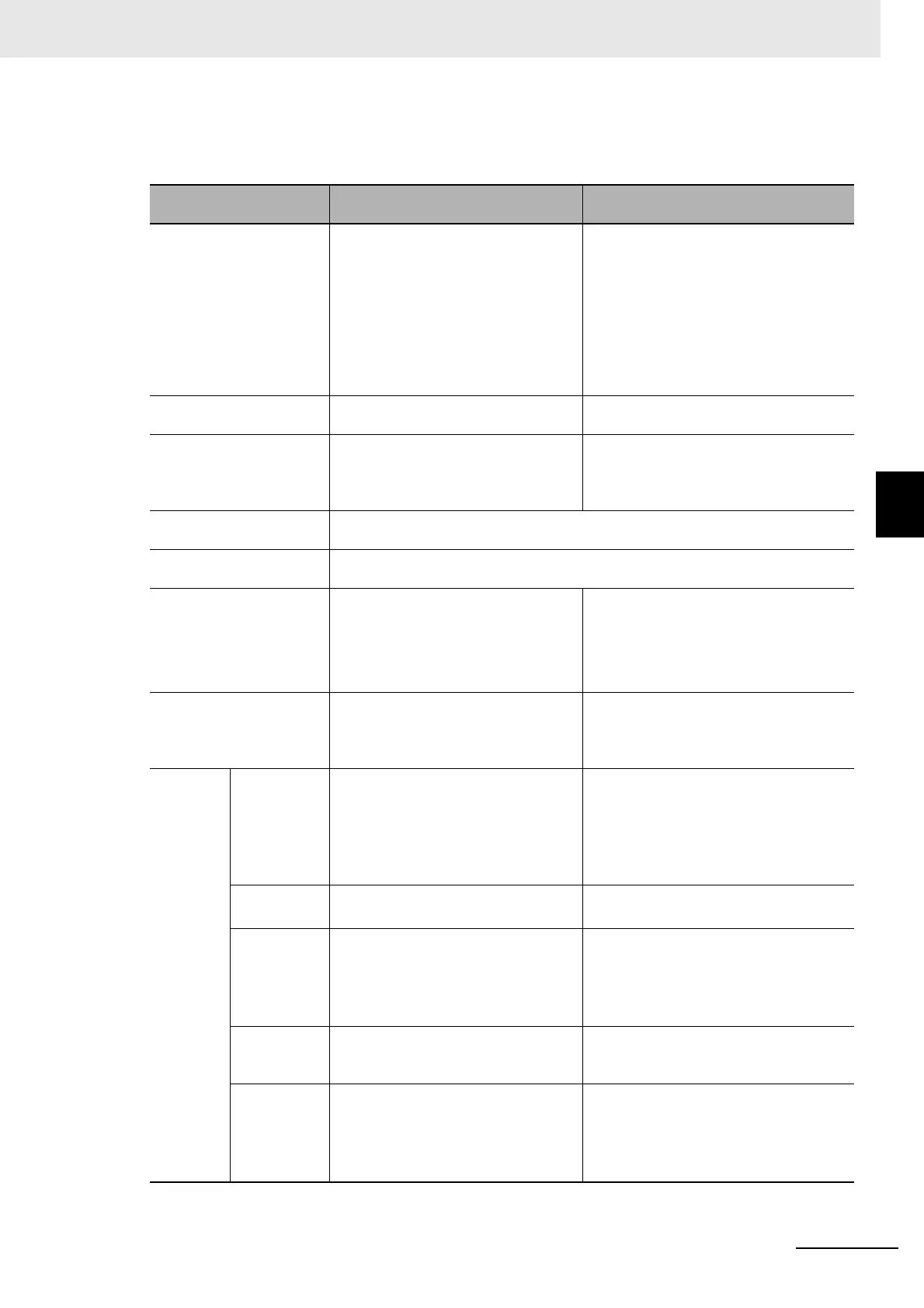
Functional Limitations of Multi-line Random-trigger Mode
Keep the following points in mind when using Multi-line Random-trigger Mode.
Item
FH series:
FH-1000/3000/5000 series
FZ5 series:
FZ5-800/1100/1200 series
Processing time • If the processing load for multiple
lines is high, there may be fluctuation
in measurement times.
• If data logging for multiple lines is to
the same drive, measurement times
may become longer.
• If the STEP signal is input at the exact
same time for lines 0 and 1, the mea-
surement on the other lines may be
delayed (roughly by the same amount
of the Camera Image Input processing
unit).
• If data logging for both Line 0 and Line
1 is to the same drive, measurement
times may become longer.
Number of Cameras The maximum number of Cameras is 8
for all lines.
The maximum number of Cameras is 2 for
all lines.
Error messages Error messages are the same for lines
0 to 7. If an error occurs on any of the
lines, an error message is displayed
and the ERROR signal is turned ON.
Error messages are the same for lines 0
and 1. If an error occurs on any of the
lines, an error message is displayed and
the ERROR signal is turned ON.
Saving data in the Control-
ler
To save data in the Controller, the data must be saved separately for each line.
Save folder for captured
images
When you click [Capture] on the Measurement Manager Bar, captured images are
always saved to the folder that is specified for line 0.
Date-time setting, lan-
guage
setting, operation mode
setting and Network drive
setting.
These settings can be set only for line
0.
These settings can be set only for line 0.
View Images can be displayed simultane-
ously for all lines. Use layout modifica-
tion to set the display position and size
for the Main Window for each line.
One of the lines must be selected to be
displayed. Both lines cannot be displayed
at the same time.
Communi-
cations
Parallel • Parallel communications can be set
only for line 0. The settings for line 0
are applied to lines 1 to 7.
• Refer to Table 1 for details on the dif-
ferences between parallel I/O and
parallel terminals.
• Parallel communications can be set
only for line 0. The settings for line 0 are
applied to line 1.
• Refer to Table 1 for details on the differ-
ences between parallel I/O and parallel
terminals.
Normal (RS-
232C/422)
RS-232C can be set only for line 0.
Lines 1 to 7 cannot be used.
RS-232C/422 can be set only for line 0.
Line 1 cannot be used.
Normal
(Ethernet)
• To use Ethernet, use a different port
number for each line.
• The IP address for the Controller
cannot be set for lines 1 to 7 (the IP
address for line 0 is used).
• To use Ethernet, use a different port
number for each line.
• The IP address for the Controller can-
not be set for line 1 (the IP address for
line 0 is used).
PLC Link
(RS-232C/
422)
RS-232C can be set only for line 0.
Lines 1 to 7 cannot be used.
RS-232C/422 can be set only for line 0.
Line 1 cannot be used.
PLC Link
(Ethernet)
• To use Ethernet, use a different port
number for each line.
• The IP address for the Controller
cannot be set for lines 1 to 7 (the IP
address for line 0 is used).
• To use Ethernet, use a different port
number for each line.
• The IP address for the Controller can-
not be set for line 1 (the IP address for
line 0 is used).
 Loading...


