Chapter 4
Clock/ Mode/ Voltage Control
IV - 24 Mode Control Function
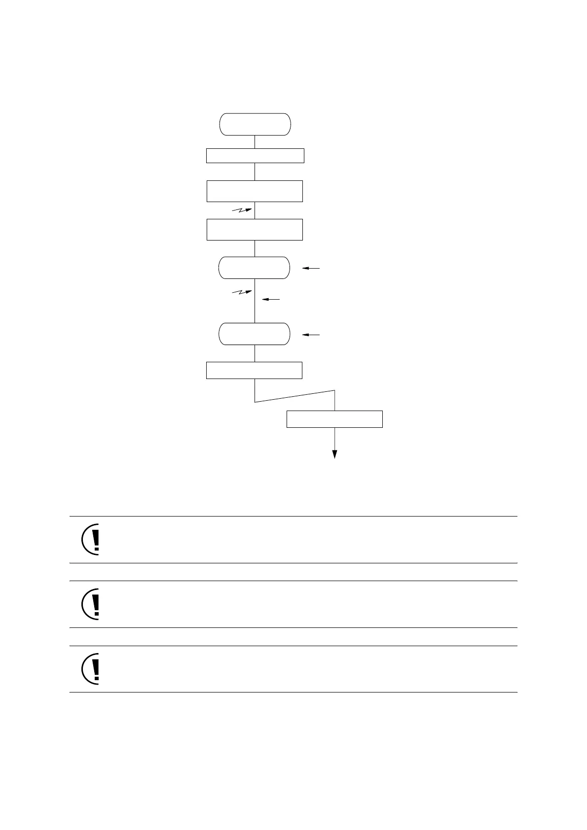
Figure:4.2.14 Operation in STANDBY Mode and Interrupt Acceptance Sequence
with Interrupt Disabled
..
Set the PSW.MIE to "0" before the transition to STANDBY mode.
..
..
Insert 3 NOP instructions right after the instruction for the transition to STANDBY mode (set-
ting to CPUM.HALT or CPUM.STOP).
..
..
The instruction for the transition to STANDBY mode must not be executed in the internal
RAM.
..
NORMAL/SLOW
mode
Disable maskable interrupts
Enable interrupt which
triggers return
Enable maskable interrupts
)
(
(
HALT/STOP
mode
NORMAL/SLOW
mode
Set HALT/STOP
mode
Interrupt service routine
Set the xICR.IE of the return factor to "1".
Set the PSW.MIE to "0",
and set all interrupt enable bits (xICR.IE) to "0"
Watchdog timer
HALT0/1/2/3 : continue counting
STOP : stop counting
eturn factor interrupt occured
eturn factor interrupt detected
When the transition corresponds to (*1) in Figure: 4.2.1,
the oscillation stabilization wait time is inserted.
Watchdog timer
HALT0/1/2/3 : continue counting
STOP : restart counting
)(
Set the PSW.MIE to "1".
 Loading...


