Chapter 4
Clock/ Mode/ Voltage Control
IV - 28 Voltage Control
Power Supply Control Register 1 (PWCTR1: 0x03F6D)
The power supply control register 1 controls CPU outage when changing the output voltage, VDD18 and Deep
STANDBY mode.
..
Set the PWCTR1.PWUPTM2-0 to match the following conditions before the transition from
1.1 V to 1.8 V or to 1.3 V.
- From 1.1 V to 1.8 V: 500 µs or more
- From 1.1 V to 1.3 V: 4 ms or more
..
..
* Only the clock supplied to CPU is halted.
The clock supplied to peripheral function is not halted. Stop the clock for each function.
..
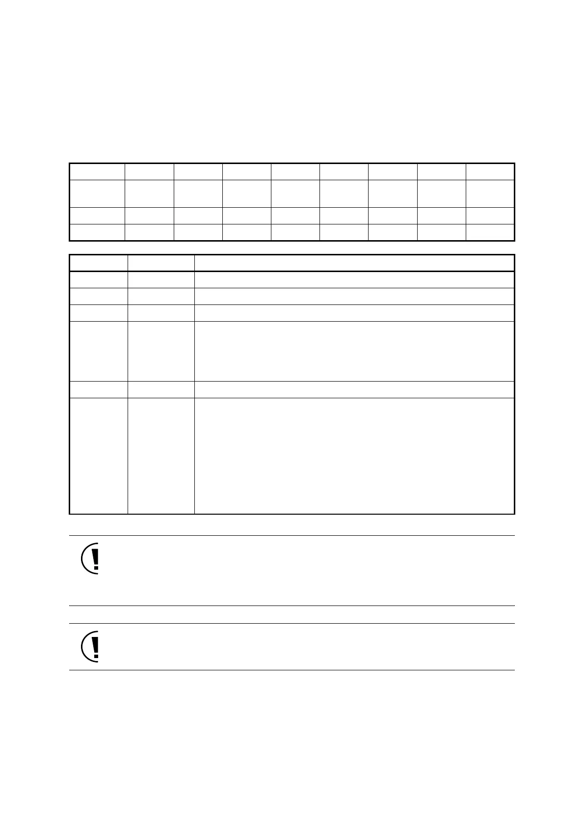
bp76543210
Bit name Reserved Reserved -
DEEP-
MOD
Reserved
PWUPTM
2
PWUPTM
1
PWUPTM
0
Initial value00001100
Access R/W R R R/W R/W R/W R/W R/W
bp Bit name Description
7 Reserved Always set to "0".
6 Reserved When transition of VDD18, set to "1" after the microcomputer starts up.
5 - Always read as "0".
4 DEEPMOD
VDD18 setting when the transition from NORMAL mode to HALT2/STOP0 mode
0: Voltage transition disabled
1: Change to 1.1 V
(Voltage returns to the same level as it was before the transition at return.
CPU starts up again after the time set in PWUPTM2-0.)
3 Reserved When transition of VDD18, set to "0" after the microcomputer starts up.
2-0 PWUPTM2-0
Set outage of CPU and clock when updating VDD18 (*)
000: 8/f
SCLK
(244 µs at f
SCLK
= 32.768 kHz)
001: 8/f
SCLK
(244 µs at f
SCLK
= 32.768 kHz)
010: 16/f
SCLK
(488 µs at f
SCLK
= 32.768 kHz)
011: 32/f
SCLK
(977 µs at f
SCLK
= 32.768 kHz)
100: 64/f
SCLK
(1953 µs at f
SCLK
= 32.768 kHz)
101: 128/f
SCLK
(3906 µs at f
SCLK
= 32.768 kHz)
110: 256/f
SCLK
(7813 µs at f
SCLK
= 32.768 kHz)
111: 512/f
SCLK
(15625 µs at f
SCLK
= 32.768 kHz)
 Loading...


