Prma 460 20 User Manual
Description
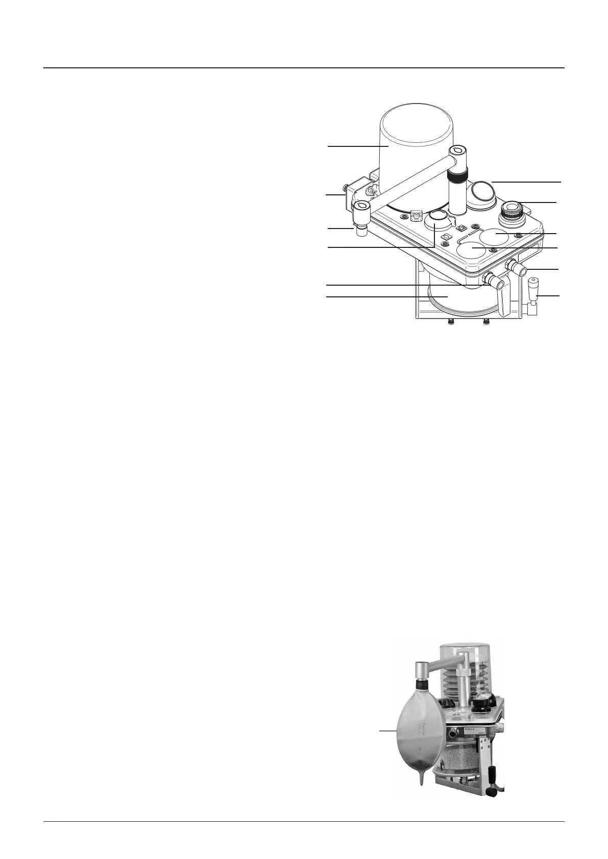
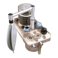
3.10.1.3 Inspiratory (3) and Expiratory (4) Non Return Valves
(NRVs)
The nspratory and expratory non-return valves are postoned
on the top of the manfold block The valves control the
drecton of the gas flow through the system
The valves conssts of a dsc located over a valve seat
The dscs operate by gravty and are retaned by gudes to
prevent lateral movement
The valves (3 and 4) are vsble through the top cover
The operaton of each valve can be vsually checked as the
patent breathes n and out
AUTION
It s mportant that the absorber s mounted uprght so that
the valve dscs move n a truly vertcal plane, wth the valve
seats horzontal
3.10.1.4 Inspiratory (5) and Expiratory (8) hose connectors
NOTE
The nspratory and expratory hose connectors are Appled
Parts
The connectors are 22 mm male and concentrc 15 mm
female, complyng wth BS EN ISO 5356/1
The drecton of flow s marked on each connector
3.10.1.5 Canister (7) and release lever (6)
The absorber must only be used when securely mounted n an
uprght poston – spllage of absorbent may contamnate the
breathng system as flows through the canster from top to
bottom
NOTE
The bag/ventlator connecton s between the absorber and the
patent
Bag squeezng or the use of mechancal ventlaton does not
result n a flow of dust towards the patent, but tends to drve
dust back nto the absorber
anster release lever
The canster release lever s located at the base of the canster
assembly
When the lever s n the vertcal poston, the canster s
locked n poston
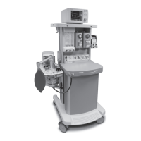
3.10.1.6 Bag/Ventilator mode switch
The bag/vent swtch (9) can be set to the reservor bag or the
ventlator postons
Ventlator mode
In ‘Ventlator’ mode the reservor bag (A) s closed off from the
breathng system and the ventlator connecton port at the rear
of the manfold block, s n crcut
WARNIN
The adustable pressure lmtng (APL) valve (2) s out of
crcut when the system s n ‘Ventlator’ mode
A
1
2
3
4
5
6
12
11
10
9
8
7