P a g e | 20 P o o l C o p M a n u a l : V 4 2 EN
www.poolcop.com PCFR
3.3 INSTALLING THE VALVE DATA UNIT
Due the large variety of possible installations, it may be necessary to adapt piping and
connectors to fit the Valve Data Unit to the filter and pump combination. Use standard and
acceptable pool plumbing parts and norms at all times.
PoolCop is supplied with a standard multiport valve housing (1.5" or 2.0").
CAUTION:
Incompatible multiport valve housings may not allow correct functioning of the automatic valve and the
filtration system, and will invalidate the warranty.
WARNING:
Verify that all electricity supply is disconnected and that the water supply is shut off prior to commencing
the installation.
Valve housing mounting on filter
For renovation, first remove the old valve housing from the filter by loosening the
filter screws
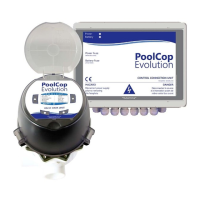
Install the PoolCop valve housing. To facilitate the installation, Filter Connection Kits
(in 1.5” or 2.0” versions) are available; these connect the supplied valve housing to
the filter bulkhead fittings. Follow Connection kit guidelines.
Figure 5 - Filter connection Kit sample
Make sure the gluing is dry and strong enough before mounting the Valve Data Unit on the valve housing.
CAUTION:
Incorrect gluing negatively affects the bonding quality and water tightness.
The valve housing is made with ABS, slip threaded pieces and PoolCop connector kits are in ABS.
Never use solvents, solvent based cleaners or primers.
Never use solvent based adhesives.
Never use glue for “flexible” or for “rigid and flexible” PVC.
ONLY lightly sand the parts to be glued.
ONLY use only provided glue.
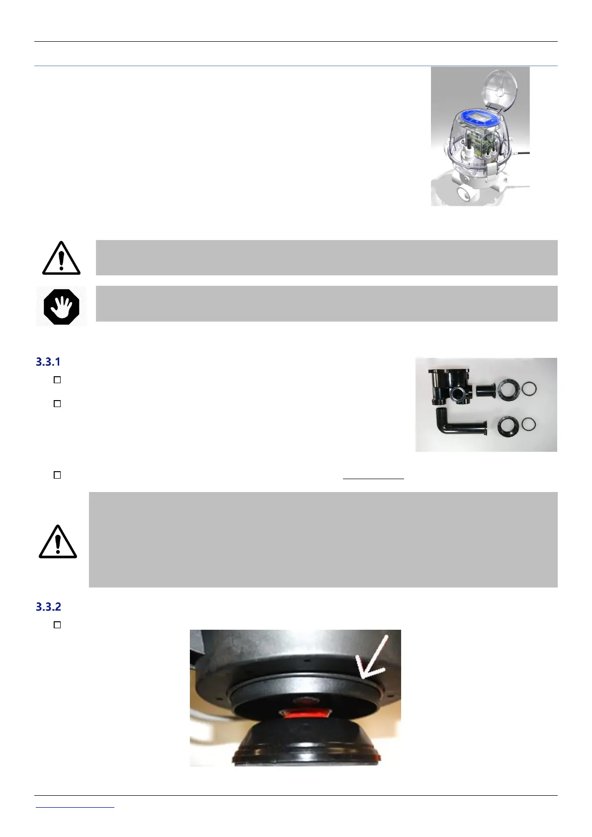
Mounting the Valve Data Unit
1.5” Valve Place the O-ring gasket on the bottom of the VDU.
Figure 6 - 1.5" valve O-ring
Figure 4- Valve Data Unit