P o o l C o p M a n u a l : V 4 2 EN P a g e | 43
www.poolcop.com PCFR
Connecting Auxiliary Relays
An auxiliary relay acts as a switch in the same way as the mechanical switch or timer:
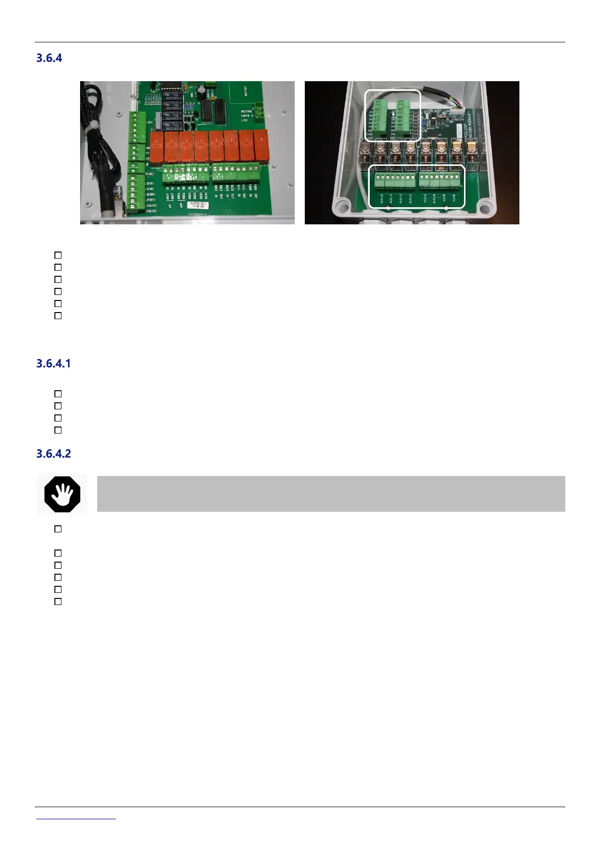
Figure 38 - Auxiliaries connection terminal in CCU (left) and in XM8 Extension Module (right)
Auxiliary relays can control auxiliary pool equipment, such as lights, heating, pool cleaners, etc.
Auxiliary Aux7 is dedicated to pH Control.
With ORP Control installed, Aux6 is dedicated to ORP Control.
With a waste valve, Aux5 is dedicated to this valve.
With Extension Module and Pool cover function installed, Aux14 is dedicated to open cover, Aux15 to close.
With Extension Module and Jetstream function installed, Aux13 is dedicated to Jetstream pump control.
Each auxiliary relay has its own dedicated timer, programmed in the PoolCop CONFIGURATION MENU. Auxiliary relays can be
given a default name or a custom name from the list available. Relays can be slaved to the pump.
Electrical Supply
The electrical supply for any of the auxiliaries can be:
110VAC mains power supply: it is recommended that the PoolCop AUX relay controls an external relay to supply power.
230VAC mains power supply: it is recommended that the PoolCop AUX relay controls an external relay to supply power.
380VAC main power supply: it is mandatory that the PoolCop AUX relay control an external relay to supply power.
24VAC on the Power Supply PCB.
Connection Instructions
In the event that the equipment to be controlled exceeds these ratings or is three-phase, the relay will be used to
command an external relay to switch the equipment.
Disconnect the supply to and from the existing auxiliary timer.
Disconnect the timer, or remove if appropriate, noting the wires that are connected to the auxiliary equipment.
Use multi-core cable to connect the auxiliary circuits to the auxiliary relays (Aux1 to Aux6) in the CCU.
The auxiliary relay functions in the same manner as a mechanical timer.
The wires should be connected in the applicable slots on connectors J6/J19 (CCU) or J1/J2(XM8) (Figure 38 - Auxiliaries
connection terminal).