P a g e | 30 P o o l C o p M a n u a l : V 4 2 EN
www.poolcop.com PCFR
3.5 WATER TREATMENT
General
PoolCop is compatible with all water treatments. There are no specific restrictions on use of any legally permitted swimming pool
water treatment with PoolCop. Follow all manufacturer recommended guidelines to ensure safety, correct dosing and equipment
life. Water treatments can be controlled using timers (slaved to filtration/circulation) or using water condition sensors and internal
algorithms.
There are three types of sensors available, the sensors have the same dimensions and fit the same housing in the PoolCop Valve
Data Unit:
pH + liquid chlorine injection; chlorine or bromine tablets
WARNING:
Certain precautions must be taken PRIOR to installation of the sensor to ensure correct measurement and to
prevent the possibility of damage: Install and test an electrical earth bonding in accordance with local
regulations. Test the water for presence of metals (iron, zinc, copper) and use a metal sequestrate treatment
in any case.
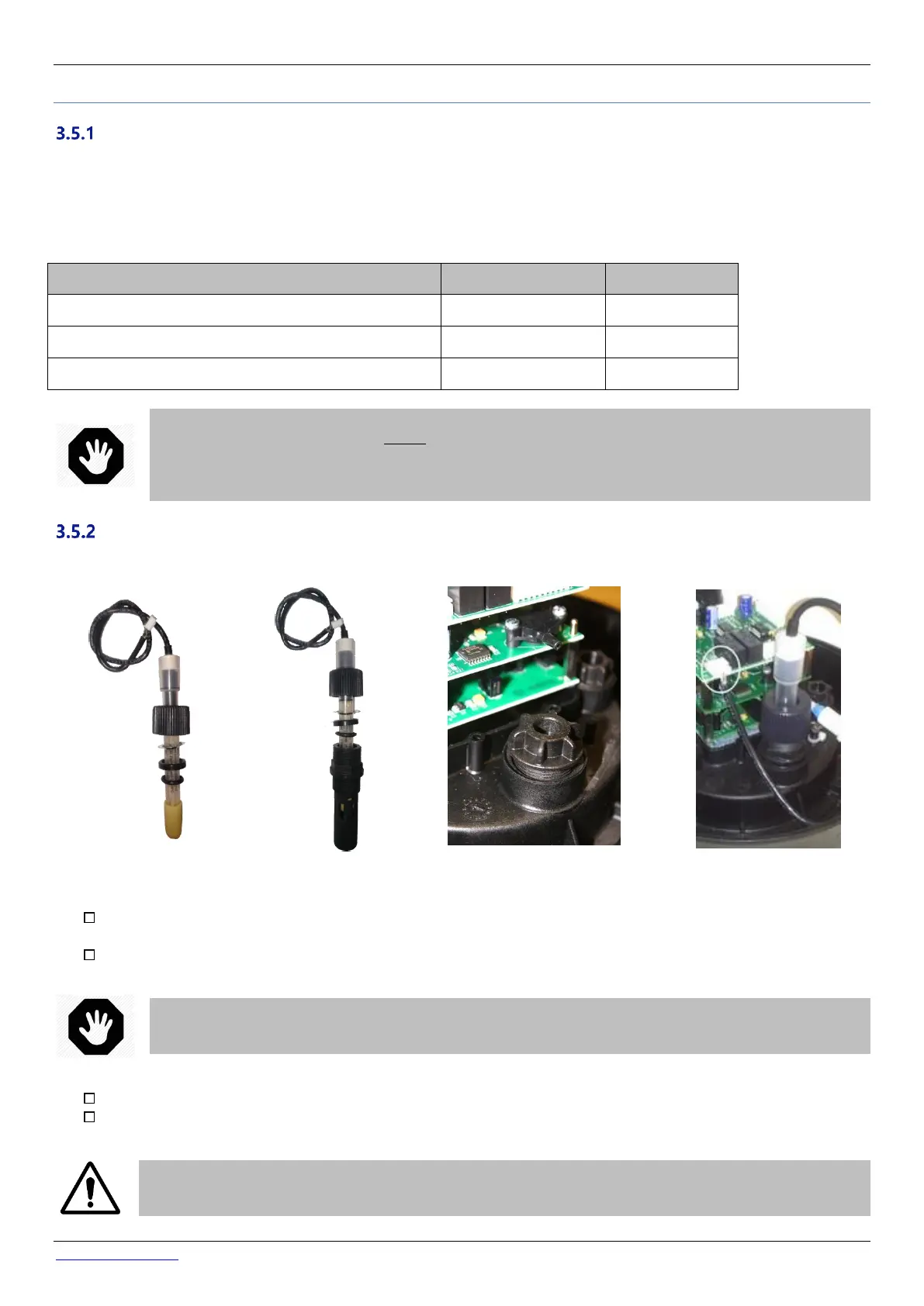
Installing the Water Condition Sensor
PoolCop has a housing in the Valve Data Unit for the water condition sensor. Installation of the sensors is the identical.
Figure 24 – PoolCop
water analysis sensor
Figure 25 - Sensor and
Housing
Figure 26 - Sensor Housing plug
Figure 27 – Sensor connection
Verify that the pump circuit breaker is OFF, and/or set all pump timers to 00:00 in FILTRATION MODES menu, with
filtration timer mode to STOPPED.
Close all valves; ensure that all possible water supplies are cut off.
WARNING:
There is a risk of flooding if the pump timers were to switch the pump ON or the water supply is not cut off.
In MANUAL CONTROL menu, select the valve to the WASTE position.
Ensure that the valve housing is depressurized and drained, by unscrewing the drain plug.
CAUTION:
Removing the electrode from the housing whilst there is pressure or a head of water in the valve and piping
can cause water to flood the Valve Data Unit causing damage to the equipment.