P a g e | 40 P o o l C o p M a n u a l : V 4 2 EN
www.poolcop.com PCFR
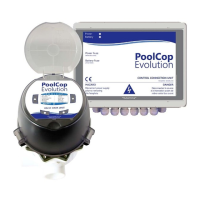
Connecting the Water Level Sensors
Before installing the water level sensor in the pool check the colours corresponding to each terminal using a multi-meter.
Ensure that the terminals are clean and free of any insulating film or grease.
Route the wire from the level sensor to the CCU. A conduit will be used to protect the cable.
Switch the CCU OFF and open the CCU.
Feed the cable through a compression gland into the CCU.
Connect the 4 cores to the connector on J20 (see Figure 35 - Connecting Water level ).
Figure 35 - Connecting Water level
CAUTION:
According to norms and regulations in place and depending on the origin of top up water, supply of fresh
water in the pool must be done in a disconnecting overflow tank so that pool water cannot flow back in the
feeding network.
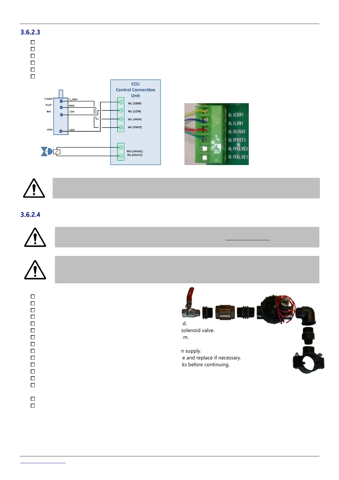
Fit a saddle onto the pool return pipe.
Drill an appropriately sized hole through the return pipe.
Fit the non-return valve and the solenoid valve.
Verify that both valves are orientated correctly.
Fit a stop valve, to shut off the main water supply when required.
Use appropriate pipe to connect the main water supply to the solenoid valve.
If buried, the pipe should be buried to a depth of at least 250mm.
If not buried, secure the pipe in a neat and adequate manner.
Once all piping and joints have been completed, open the main supply.
Verify that the solenoid valve closes and seals correctly. Remove and replace if necessary.
Verify all piping, joints, and connections for leaks. Repair all leaks before continuing.
If necessary, extend the 2-core wire of the electrical solenoid.
Feed the cable through a compression gland into the CCU.
Connect the 2 core wire from the valve solenoid to the connector on J13 marked SOL (24V AC) according to Figure 35 -
Connecting Water level. Polarity is not important.
Reconnect electrical power supply to the PoolCop CCU.
Switch the CCU ON.