P o o l C o p M a n u a l : V 4 2 EN P a g e | 41
www.poolcop.com PCFR
Installing XM8 Extension Module
The electric standard applicable is HD60364-7-702. It is obligatory that your installation adheres to the criteria of this standard.
The XM8 Extension Module provides 8 extras digital multipurpose inputs and 8 extras digital outputs (relays).
Relays usage will be defined in AUXILIARIES menu (see 5.3 Auxiliaries Menu for details).
Inputs usage will be defined in INPUTS menu (see 5.6.4 Inputs for more details).
With the Extension Module, some extras functionalities are available such as Pool cover control or Jetstream control (see 5.6.6
Equipment for more details).
XM8 box is provided with compression glands size PG7 (for external diameter 3.5mm to 8mm), PG9 (for external diameter 3.5mm to
8mm) and PG11 (for external diameter 4mm to 10mm). The cables must pass through the appropriate compression gland size
according their diameter and the compression gland must be tightened to secure the cable.
Cables selection:
For auxiliary control: H03VV or H05VV with section 2x0.75.
Smaller sections and multiple conductor cables can be used depending on amperage (ex JZ-500 12x0.5).
Installing:
Mount the XM8 in a weather-proof location close to the CCU. Ensure the unit is secured. The Unit is provided with 4 screws
and 4 concrete plastic expansion plugs. Make sure the wall material is compliant with these kinds of plugs or use the
correct plugs.
NOTE:
The connection cable between CCU and Extension Module is 1.2 meter long.
Make sure these modules are close enough to route the connection cable properly.
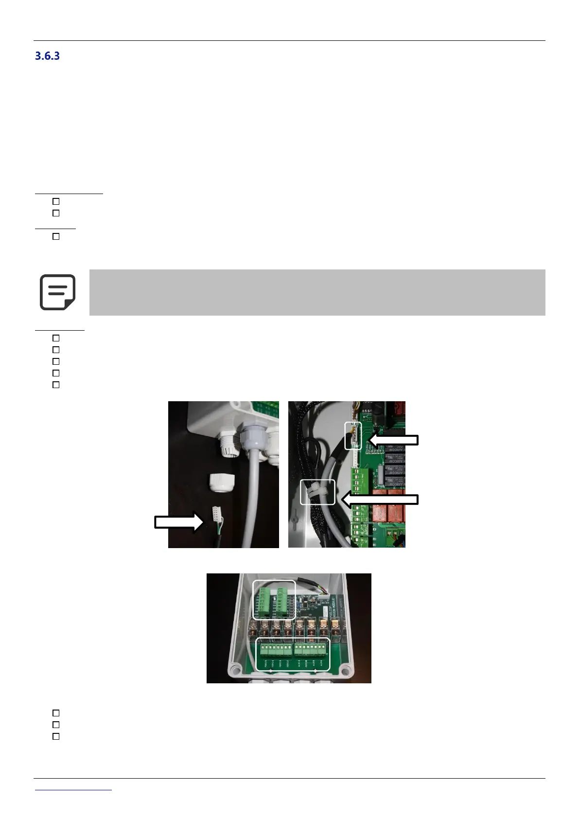
Connecting:
Shut the CCU power down.
Open the CCU cover and the XM8 cover with a screw driver.
Pass the cable for the XM8 Extension Module through a compression gland of the CCU and secure it.
Connect the cable extremity to J23 or J24.
The Extension Module will be powered by 12Vdc provided by CCU. No need for an external power supply.
Figure 36 - Cables entries
Figure 37 – Terminals
See the appropriate section of this manual for connection details.
Feed auxiliary equipment supply cables through a compression gland into the Extension Module.
Switch the CCU ON.