P o o l C o p M a n u a l : V 4 2 EN P a g e | 21
www.poolcop.com PCFR
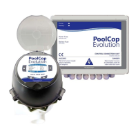
2.0” Valve Place the O-ring gasket on the 2.0” adapter.
Figure 7 - 2.0" valve O-ring
Fit the Valve Data Unit with O-ring into the multiport valve housing.
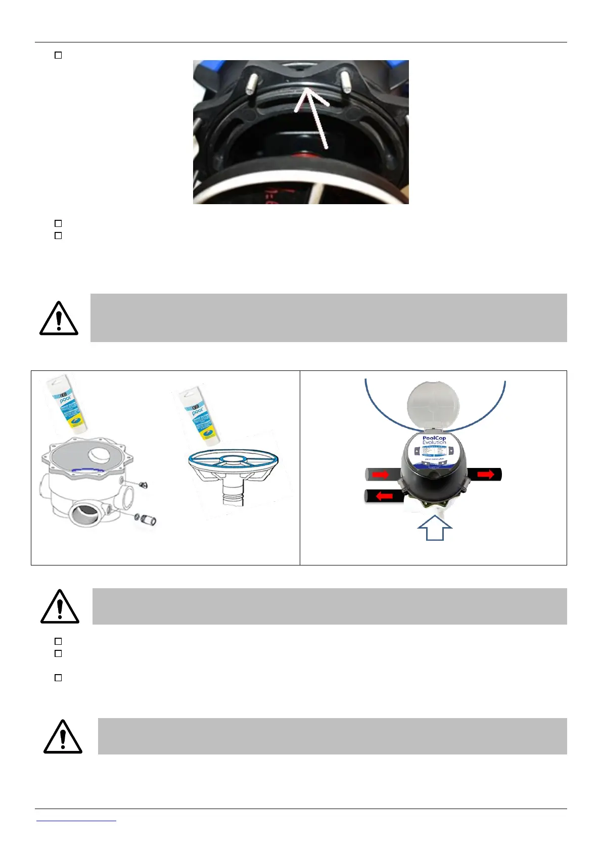
Verify the orientation of the Valve Data Unit:
o SIDE MOUNT On a standard side mount sand filter the Valve Data Unit hinge will be closest to the filter and
directly above the filter connector pipes. The waste pipe will be on the right-hand side.
o TOP MOUNT On a standard top mount filter, check the alignment indicator on the valve housing and ensure
that the waste pipe is at the three o’clock position with respect to the PoolCop Valve Data Unit.
CAUTION
Apply a layer of pure silicon grease provided) on the wagon wheel gasket and inside the valve housing. You
can also apply some grease or lubricant to the O-ring gaskets.
.
Figure 8 – Wagon wheel gasket
and valve housing greasing
Figure 9 - Orientation viewed from the top of
the Valve Data Unit
CAUTION:
Verify that the Valve Data Unit is correctly orientated before continuing.
Using a spherical head 5mm Allen key and 10mm open spanner:
1.5” Valve: Secure the Valve Data Unit to the valve housing using the 4 short and 2 long cap screws and all 6 nuts (the flat
washers will be placed under the heads of the cap screws).
2.0” Valve: Verify that the Valve Data Unit is correctly secured to the 2.0” adapter ring by means of the 4 short and 2 long
cap screws into the captive nuts in the adapter ring (with flat washers placed under the heads of the cap screws). Using a
5mm spherical head Allen key, secure the adapter ring to the valve housing using the 10 cap screws and nuts.
CAUTION:
Fasten in a cross-over sequence.
Do not over-tighten the screws.