P a g e | 22 P o o l C o p M a n u a l : V 4 2 EN
www.poolcop.com PCFR
3.4 INSTALLING THE CONTROL CONNECTION UNIT
Electrical connection
The electric standard applicable is HD60364-7-702 (NFC15-100 in France). It is obligatory that your installation adheres to the
criteria of this standard. When installing the device, the installer must ensure that the circuitry is protected by a 30mA
differential circuit breaker. He must also ensure a bipolar external mean to remove electrical power to the device so that
maintenance operations can be done safely.
CCU box is provided with compression glands size PG9 (for external diameter 3.5mm to 8mm), PG11 (for external diameter 4mm to
10mm) and PG13.5 (for external diameter 6mm to 12mm). The cables must pass through the appropriate compression gland size
according their diameter and the compression gland must be tightened to secure the cable.
Cables selection:
For CCU electric power supply: H03VV or H05VV with section 3G0.75.
For pump and auxiliary control: H03VV or H05VV with section 2x0.75.
Smaller sections and multiple conductor cables can be used depending on amperage (ex JZ-500 12x0.5).
Installing:
Mount the CCU in a weather-proof location. Ensure the unit is secured. The Unit is provided with 4 screws and 4 concrete
plastic expansion plugs. Make sure the wall material is compliant with these kinds of plugs or use the correct plugs.
Connecting:
Open the Control Connection Unit (CCU) cover with a screw driver.
Remove the Power Supply Card PCB located on J22.
Disconnect the battery.
Feed the VDU Data Link cable through the hole on the bottom left of the CCU.
Secure the cable.
Connect the 7-pin connection to J4 and the 9-pin connection to J5.
Connect the RJ45 male end to the RJ45 pass-through connector.
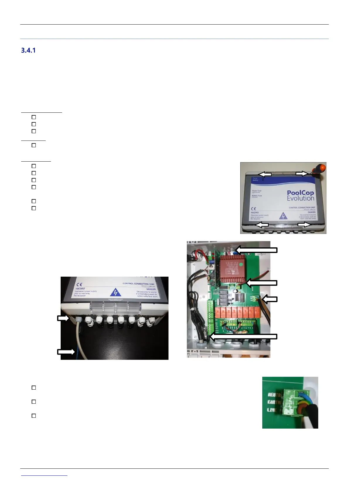
Figure 10 - Cables entries
Connect the CCU cable to the electrical supply from the distribution box using a 2A bipolar
circuit breaker
In the Control Connection Unit, make sure to respect the wiring order onto the power
terminal: Live and neutral are on the edges. Protective earth is in the middle.
Before powering up:
o Check the 115V/220V selector position; slide selector to the left for 220/240VAC
power supply, slide to the right for 115/120VAC.
o Check that the internal switch on the electronic board in ON.