P o o l C o p M a n u a l : V 4 2 EN P a g e | 39
www.poolcop.com PCFR
Water Level Control
Automatic water level control functionality is integrated. In order to benefit from this feature, the optional water level sensor and
valve kit is required. After installation, activate and program Water Level Control in the Configuration menu (See 5.4.1. Water Level).
When ready to commence the installation, the installer must:
Disconnect all electrical power to the pool and systems.
Close all valves, and if necessary block all inlets to and outlets from the pool. This will prevent water from flowing to the
multiport valve and into the pump house during installation.
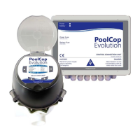
Installing the Water Line Version, with 4 Terminals
Secure the water level sensor (using stainless steel
self-tapping screws, or appropriate adhesive) at the
correct height on the inside of the skimmer or on the
waterline.
If the level sensor is fitted in the skimmer, make sure
that the skimmer basket and lid can easily be
removed and replaced without damaging the sensor
or cable.
Normal water level must be between WL (HIGH) and
WL (LOW)
WL (HIGH) must be below pool overflow level and at
an appropriate level with regards to the skimmer.
WL (PROT) is the V.HIGH level, at maximum pool
water level.
Figure 33 –Water line level sensor
Table 2 Water Line Version 4 Terminals, Cable and Connection
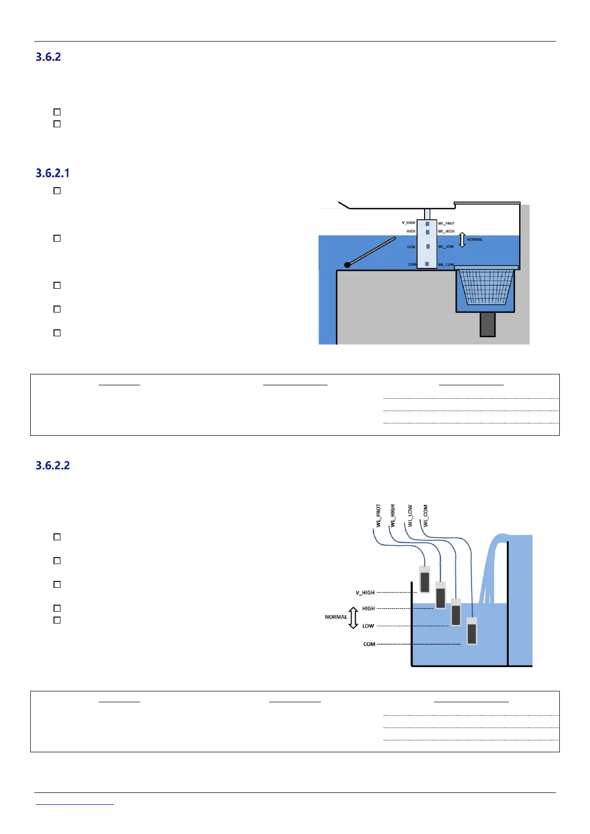
Installing the Buffer Tank Version, with 4 Sensors (Infinity Pools)
The 4 sensors are identical, with the same colour cable.
Add tags/labels prior to installation to identify the correct cable and sensor.
Check that the pool water level is correct and that the
buffer tank level is correct.
Secure the 4 water level sensors at the correct
respective heights in the buffer tank.
Normal tank level must be between WL (HIGH) and WL
(LOW)
WL (HIGH) must be below tank overflow level.
WL (PROT) is the V.HIGH level, at maximum tank water
level.
Figure 34 - Buffer tank water level sensors
Table 3 Buffer tank Version, with 4 sensors