P o o l C o p M a n u a l : V 4 2 EN P a g e | 23
www.poolcop.com PCFR
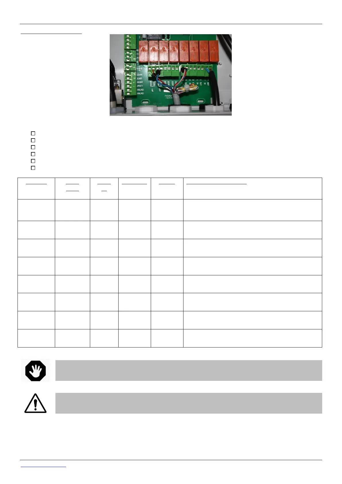
Relay output connection:
Figure 11 – Terminals
The pump relay K1 is a dedicated relay for primary pump control, and will not be used for other functions.
Auxiliaries can be connected via relays K2 – K7.
See the appropriate section of this manual for connection details.
Feed auxiliary equipment control cables through appropriate compression gland into the CCU.
When using multi strand cable, use a cable end.
Always cramp the cable ends together as close as possible to the connector (see Figure 11 – Terminals above)
A single phase pump power supply up to 1100W can be
switched directly by the relay; although it is not
recommended to switch the pump directly.
Pool heating relay control, etc.
Pool cleaner booster pump, etc.
Garden lighting, irrigation control, etc.
Pool treatment equipment, etc.
Water treatment, etc.
This relay dedicated to integrated ORP if installed.
Table 1 Relays and Power Ratings
WARNING:
Never exceed the power ratings.
Always conform to local installation norms and requirements.
CAUTION:
If you are unsure of the applicable wattage rating, contact the distributor of the auxiliary apparatus to
confirm prior to connection.