Mechanical Installation
2
2.7 Removing/Reattaching Covers
SIEPYEUOQ2A01G AC Drive Q2A Technical Manual 45
1. Wire the drive and other peripheral devices.
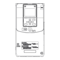
2. Reverse the steps to reattach the cover.
Note:
• Wire the grounding terminals first, main circuit terminals next, and control circuit terminals last.
• Make sure that you do not pinch wires or signal lines between the front cover and the drive before you reattach the cover.
• Tighten the screws to a tightening torque of 0.98 N∙m to 1.33 N∙m (8.67 lb.∙in. to 11.77 lb.∙in.).
Figure 2.23 Reattach the Front Cover
3. Reattach the keypad to the original position.
◆ Remove the Front Cover of Drive Models 2257 - 2415, 4208 - 4675
DANGER! Electrical Shock Hazard. Electrical Shock Hazard. Do not examine, connect, or disconnect wiring on an energized
drive. Before servicing, disconnect all power to the equipment and wait for the time specified on the warning label at a minimum.
The internal capacitor stays charged after the drive is de-energized. The charge indicator LED extinguishes when the DC bus
voltage decreases below 50 Vdc. When all indicators are OFF, measure for dangerous voltages to make sure that the drive is
safe. If you do work on the drive when it is energized, it will cause serious injury or death from electrical shock.
1. Loosen the screws on the terminal cover, then pull down on the cover.
CAUTION! Crush Hazard. Only loosen the cover screws. Do not fully remove the cover screws. Make sure that the
terminal covers for larger drives do not fall. Missing cover screws can cause the terminal cover to fall and cause injury.
Figure 2.24 Loosen the Terminal Cover Mounting Screws
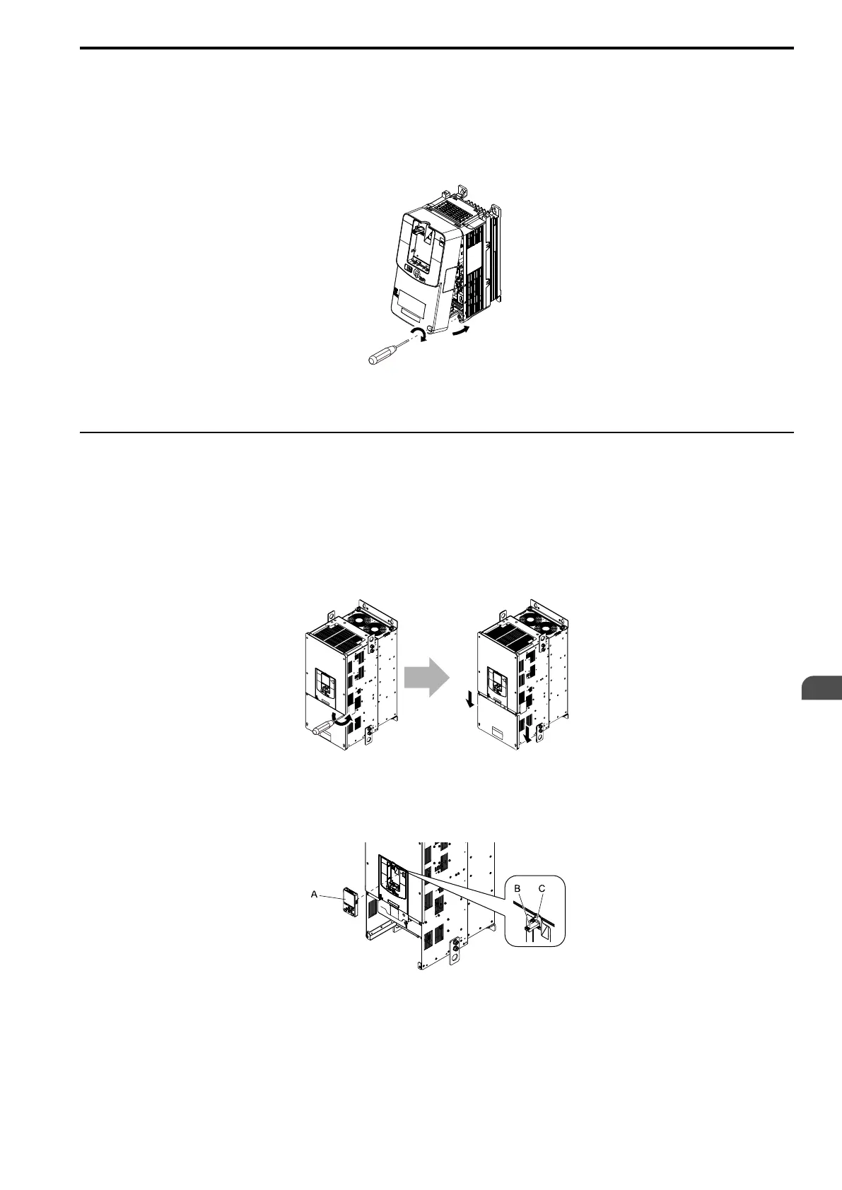
2. Pull the terminal cover away from the drive.
3. Remove the keypad, and keypad connector, then insert the end of the keypad connector that has the tab
into the keypad connector holder on the front cover.
A - Keypad
B - Keypad connector
C - Connector holder
Figure 2.25 Remove the Terminal Cover, Keypad, and Keypad Connector