Electrical Installation
3
3.5 Control Circuit Wiring
SIEPYEUOQ2A01G AC Drive Q2A Technical Manual 91
Table 3.9 Monitor Output
Terminal Name (Default) Function (Signal Level)
PO
Pulse train output
(Output frequency)
32 kHz (maximum)
Refer to “Pulse Train Output” on page 96 for more information.
AO1
Analog monitor output 1
(Output frequency)
Select voltage or current output.
• 0 V to 10 V/0% to 100%
• -10 V to +10 V/-100% to +100%
• 4 mA to 20 mA (receiver recommended impedance: 250 Ω)
Note:
Select with jumper switch S5 and H4-07 [AO1 Signal Level Select] or H4-08 [AO2 Signal Level Select].
AO2
Analog monitor output 2
(Output current)
A0V Monitor common 0 V
■ External Power Supply Input Terminals
This chapter contains a list of the functions of the external power supply input terminals.
Table 3.10 External Power Supply Input Terminals
Terminal Name (Default) Function
E24V External 24 V power supply input
Supplies backup power to the drive control circuit, keypad, and option board.
21.6 VDC to 26.4 VDC, 700 mA
A0V External 24 V power supply ground 0 V
■ Serial Communication Terminals
This chapter contains a list of the functions of serial communication terminals and functions.
Table 3.11 Modbus Communication
Terminal Terminal Name Function (Signal Level)
RS485+ Communication input/output (+)
Modbus communications
Use an RS-485 cable to connect the drive.
Note:
Set DIP switch S2 to ON to enable the termination
resistor in the last drive in a Modbus network.
• RS-485
• Modbus communication protocol
• Maximum 115.2 kbps
RS485- Communication output (-)
A0V Signal ground
0 V
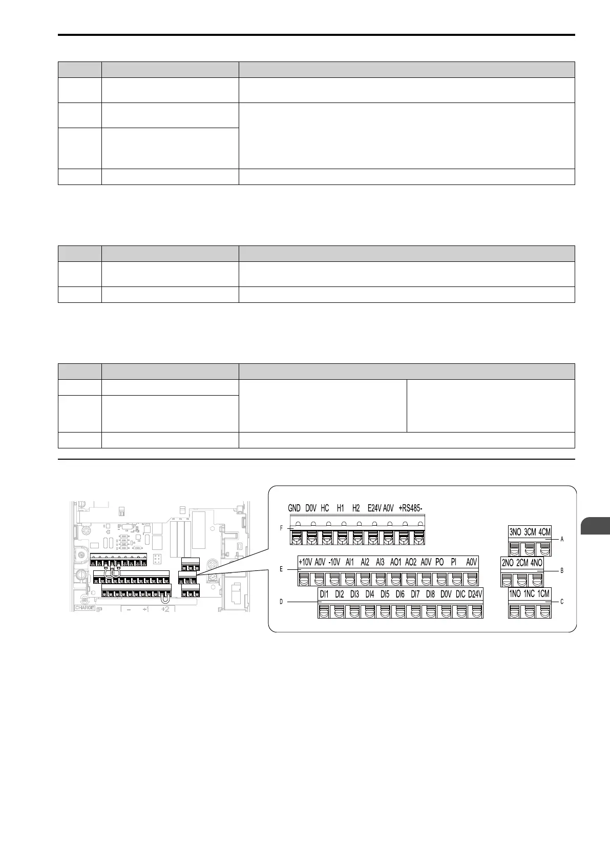
◆ Control Circuit Terminal Configuration
A - Terminal block (TB2-3)
B - Terminal block (TB2-2)
C - Terminal block (TB2-1)
D - Terminal block (TB1)
E - Terminal block (TB3)
F - Terminal block (TB4)
Figure 3.34 Control Circuit Terminal Arrangement
Use the tables in this section to select the correct wires. Use shielded wire for the control circuit terminal block.
Use crimp ferrules on the wire ends to make wiring easier and more reliable.