3.5 Control Circuit Wiring
94 SIEPYEUOQ2A01G AC Drive Q2A Technical Manual
A - Wire with a crimp ferrule attached, or
unsoldered wire with the core wires lightly
twisted
B - Pull back the shielding and lightly twist the end
with your fingers to keep the ends from fraying.
C - Remove approximately 5.5 mm (0.21 in.) of the
covering at the end of the wire if you do not use
crimp ferrules.
Figure 3.39 Wiring Procedure for the Control Circuit
Note:
• Do not solder the core wire. Soldered wire connections can become loose over time and cause unsatisfactory drive
performance.
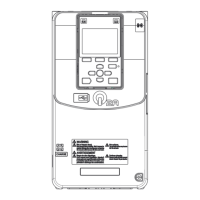
• Prepare the wire ends of shielded twisted-pair wires as shown in Figure 3.40 to use an analog reference from an external
frequency setting potentiometer to set the frequency. Connect the shield to terminal GND of the drive.
A - Connect the cable sheath to terminal GND of
the drive.
B - Sheath
C - Insulate with electrical tape or shrink tubing.
Figure 3.40 Preparing Ends of Shielded Cable
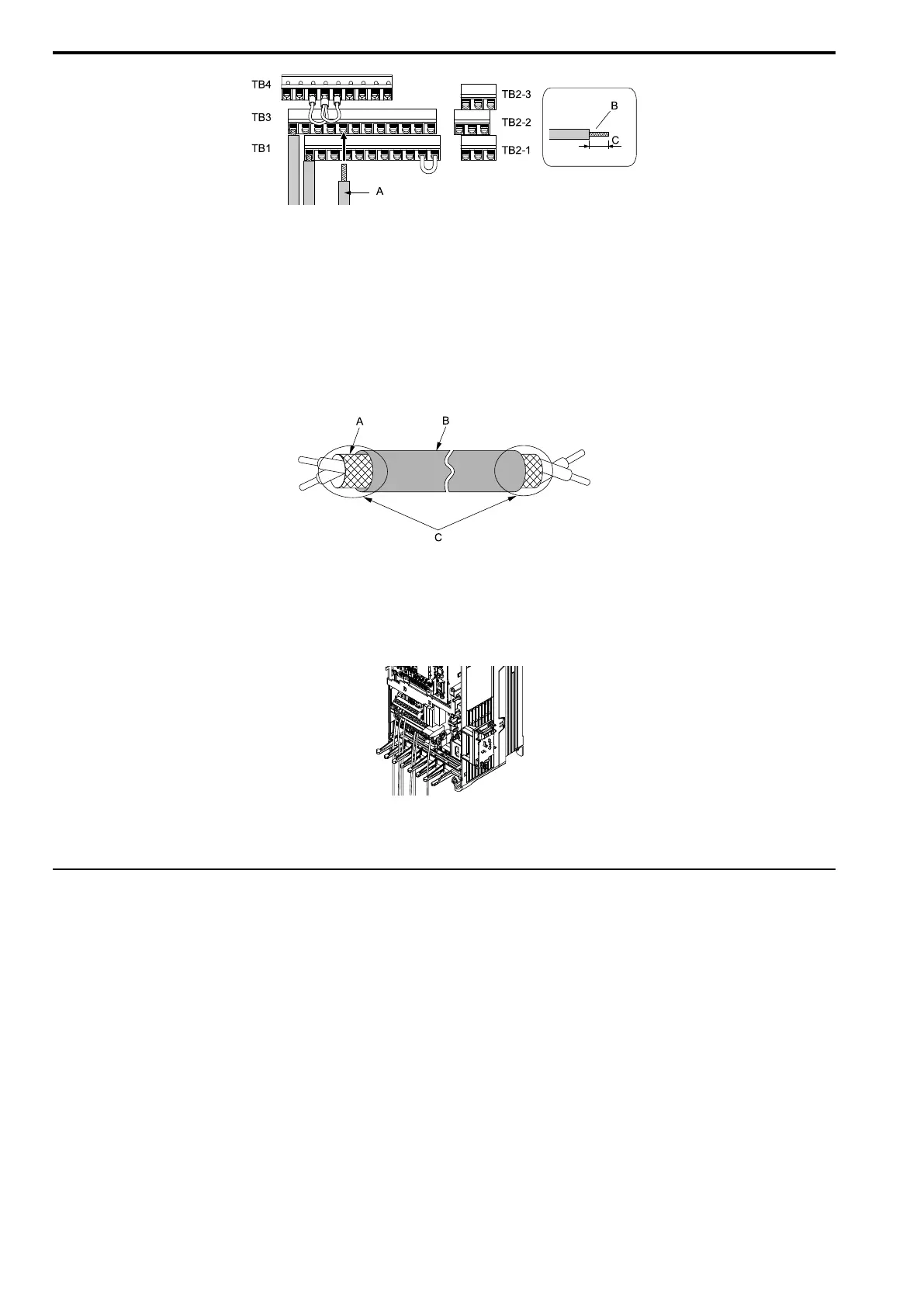
3. Put the cable through the clearance in the wiring cover.
Figure 3.41 Control Circuit Wiring
4. Install the USB port board, front cover, and the keypad to their initial positions.
◆ Switches and Jumpers on the Terminal Board
The terminal board has switches to adapt the drive I/Os to the external control signals.
Set the switches to select the functions for each terminal.