Electrical Installation
3
3.5 Control Circuit Wiring
SIEPYEUOQ2A01G AC Drive Q2A Technical Manual 95
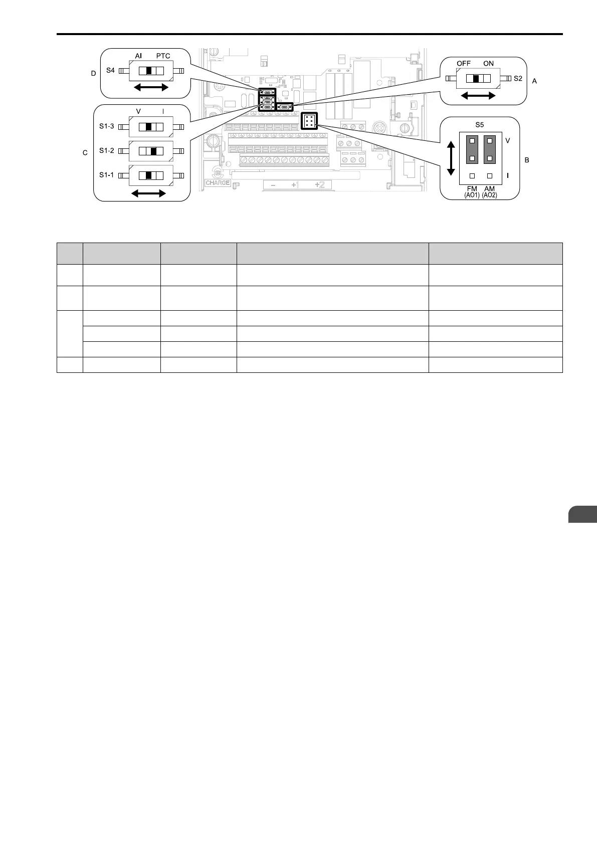
Figure 3.42 Locations of Switches
Table 3.14 I/O Terminals and Switches Functions
Posi
tion
Switch Terminal Function Default Setting
A DIP switch S2 -
Enables and disables the Modbus communications termination
resistor.
OFF
B Jumper switch S5 AO1, AO2 Sets terminals AO1 and AO2 to voltage or current output.
AO1: V (voltage output)
AO2: V (voltage output)
C
DIP switch S1-1 AI1 Selects the input signal type (voltage/current). V (voltage input)
DIP switch S1-2 AI2 Selects the input signal type (voltage/current). I (current input)
DIP switch S1-3 AI3 Selects the input signal type (voltage/current). V (voltage input)
D DIP switch S4 AI3 Selects MFAI or PTC input. AI (analog input)