3.5 Control Circuit Wiring
90 SIEPYEUOQ2A01G AC Drive Q2A Technical Manual
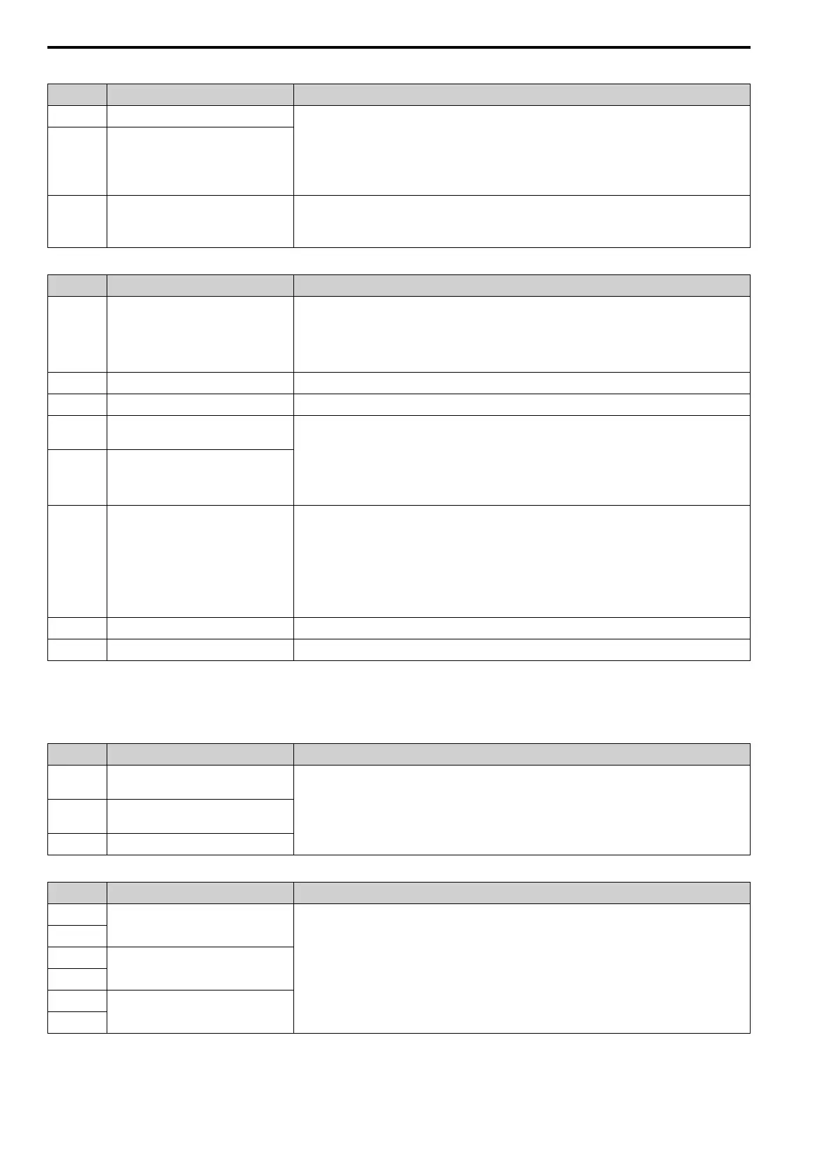
Table 3.5 Safe Disable Input
Terminal Name (Default) Function (Signal Level)
H1 Safe Disable input 1
Remove the jumper between terminals H1-HC and H2-HC to use the Safe Disable input.
• 24 V, 6 mA
• ON: Normal operation
• OFF: Coasting motor
• Internal impedance 4.7 kΩ
• OFF Minimum OFF time of 2 ms.
H2 Safe Disable input 2
HC Safe Disable function common
Safe Disable function common
NOTICE: Do not close the circuit between terminals HC and D0V. Failure to obey
will cause damage to the drive.
Table 3.6 Master Frequency Reference
Terminal Name (Default) Function (Signal Level)
PI
Master frequency reference pulse train input
(Master frequency reference)
• Response frequency: 0 Hz to 32 kHz
• H level duty: 30% to 70%
• H level voltage: 3.5 V to 13.2 V
• L level voltage: 0.0 V to 0.8 V
• Input impedance: 3 kΩ
+10V Power supply for frequency setting 10.5 V (allowable current 20 mA maximum)
-10V Power supply for frequency setting -10.5 V (allowable current 20 mA maximum)
AI1
MFAI1
(Master frequency reference)
Voltage input or current input
Select terminal AI1 with DIP switch S1-1 and H3-01 [AI1 Signal Level Select].
Select terminal AI2 with DIP switch S1-2 and H3-09 [AI2 Signal Level Select].
• -10 V to +10 V/-100% to +100% (input impedance: 20 kΩ)
• 0 V to 10 V/100% (input impedance: 20 kΩ)
• 4 mA to 20 mA/100%, 0 mA to 20 mA/100% (input impedance: 250 Ω)
AI2
MFAI2
(Combined to terminal A1)
AI3
MFAI3/PTC input
(Auxiliary frequency reference)
• Voltage input or current input
Select with DIP switch S1-3 and H3-05 [AI3 Signal Level Select].
– -10 V to +10 V/-100% to +100% (input impedance: 20 kΩ)
– 0 V to 10 V/100% (input impedance: 20 kΩ)
– 4 mA to 20 mA/100%, 0 mA to 20 mA/100% (input impedance: 250 Ω)
• PTC input (Motor Overheat Protection)
Set DIP switch S4 to “PTC” and set DIP switch S1-3 to “V” to set terminal AI3 for PTC input.
A0V Frequency reference common 0 V
GND Connecting shielded cable -
■ Output Terminals
This chapter contains a list of output terminals and functions.
Table 3.7 Fault Relay Output
Terminal Name (Default) Function (Signal Level)
1NO
N.O. output
(Fault) • Relay output
• 30 Vdc, 10 mA to 1 A
• 250 Vac, 10 mA to 1 A
• Minimum load: 5 V, 10 mA (Reference value)
1NC
N.C. output
(Fault)
1CM Digital output common
Table 3.8 MFDO
Terminal Name (Default) Function (Signal Level)
2NO
MFDO
(During run)
• Relay output
• 30 Vdc, 10 mA to 1 A
• 250 Vac, 10 mA to 1 A
• Minimum load: 5 V, 10 mA (Reference value)
Note:
Do not set functions that frequently switch ON/OFF to MFDO (2NO to 4CM) because this will decrease the
performance life of the relay contacts. The manufacturer estimates switching life at 200,000 times (assumes 1
A, resistive load).
2CM
3NO
MFDO
(Zero speed)
3CM
4NO
MFDO
(Speed agree 1)
4CM