12.6 F: OPTIONS
654 SIEPYEUOQ2A01G AC Drive Q2A Technical Manual
1 : AB Pulse Detection
■ F1-30 M2 Enc PCB Port Select
No.
(Hex.)
Name Description
Default
(Range)
F1-30
(03AA)
M2 Enc PCB Port Select
Sets the drive port to install the motor 2 encoder option card.
1
(0, 1)
0 : CN5-C
One option card receives the speed feedback signals from motor 1 and motor 2.
1 : CN5-B
Two option cards receive the speed feedback signals from motor 1 and motor 2.
■ F1-31 Enc2 Pulse Count (PPR)
No.
(Hex.)
Name Description
Default
(Range)
F1-31
(03B0)
Enc2 Pulse Count (PPR)
Sets the number of output pulses for each motor revolution for motor 2.
1024 ppr
(1 - 60000 ppr)
■ F1-32 Enc2 Rotat Selection
No.
(Hex.)
Name Description
Default
(Range)
F1-32
(03B1)
Enc2 Rotat Selection
Sets the output sequence for the A and B pulses from the encoder for motor 2. This parameter
assumes that the motor is operating in the forward direction.
0
(0, 1)
Refer to the option card installation manual for more information about how to set the encoder pulse output
sequence and make sure that it is correct.
0 : A leads in FWD Direction
1 : B leads in FWD Direction
■ F1-33 Enc2 Gear Teeth1
No.
(Hex.)
Name Description
Default
(Range)
F1-33
(03B2)
Enc2 Gear Teeth1
Sets the number of gear teeth on the motor side for motor 2. This parameter and F1-34 [Enc2
Gear Teeth2] set the gear ratio between the motor and encoder.
0
(0 - 1000)
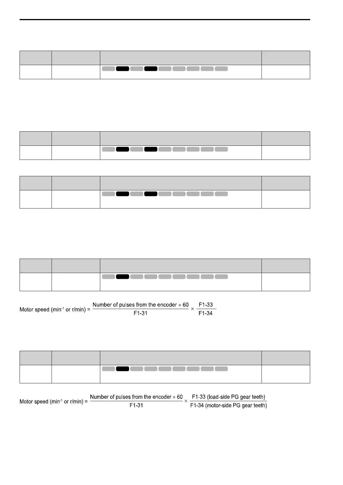
After you set the number of gear teeth, the drive uses this formula to calculate the motor speed:
Note:
When F1-33 = 0 or F1-34 = 0, the gear ratio is 1.
■ F1-34 Enc2 Gear Teeth2
No.
(Hex.)
Name Description
Default
(Range)
F1-34
(03B3)
Enc2 Gear Teeth2
Sets the number of gear teeth on the load side for motor 2. This parameter and F1-33 [Enc2 Gear
Teeth1] set the gear ratio between the motor and encoder.
0
(0 - 1000)
After you set the number of gear teeth, the drive uses this formula to calculate the motor speed:
Note:
When F1-33 = 0 or F1-34 = 0, the gear ratio is 1.
 Loading...