Serial Bus Analysis
R&S
®
RTC1000
125User Manual 1335.7352.02 ─ 02
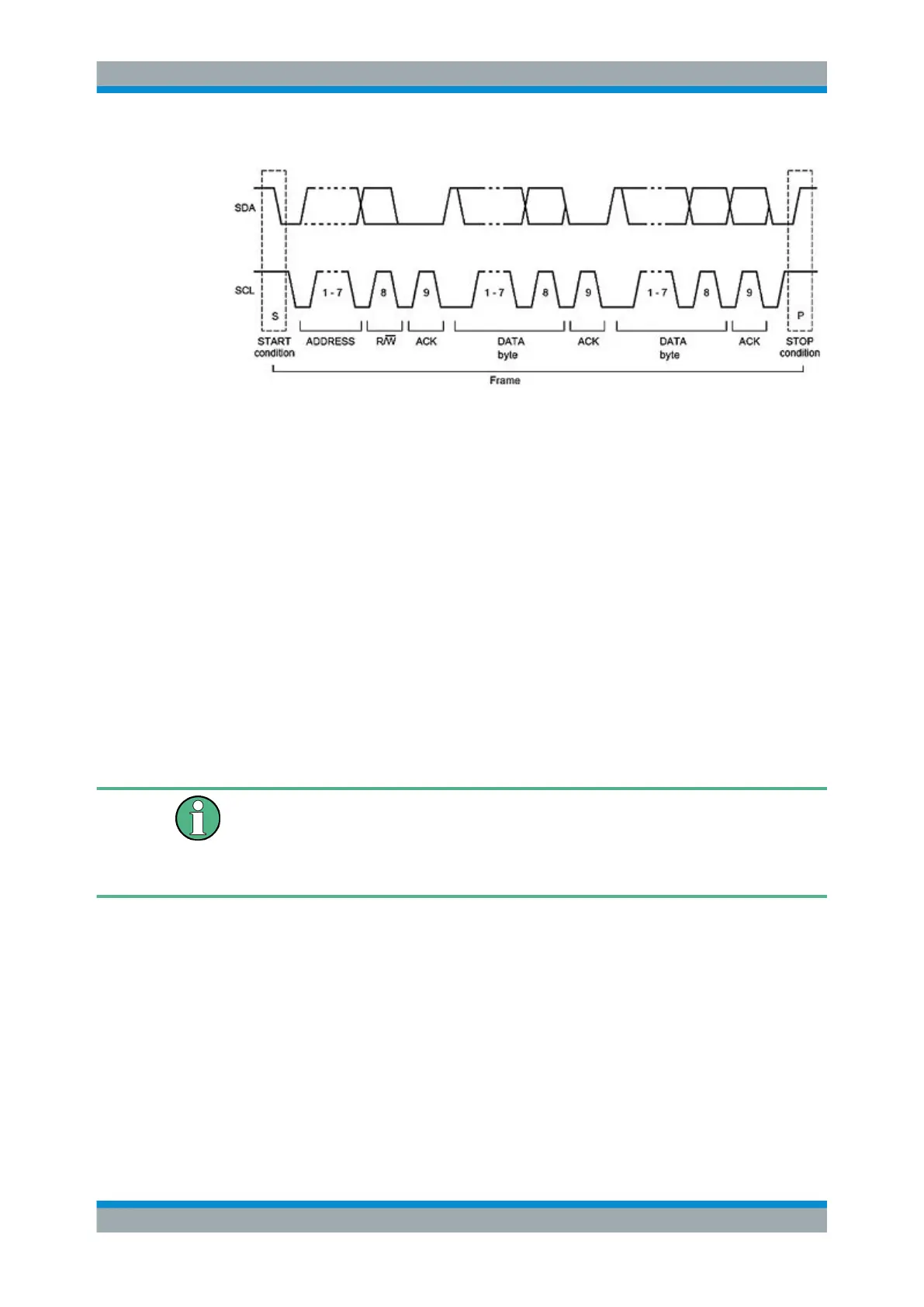
Figure 11-3: I2C 7-bit address
The format of a simple I
2
C message (frame) with an address length of 7 bit has the
following structure:
●
Start condition: falling slope on SDA (serial data), while SCL (serial clock) is high
●
7-bit address (write or read slave)
●
Read/Write bit (R/W): indicates if the data is to be written or read out from the slave
●
Acknowledge bit (ACK): is issued by the recipient of the previous byte if transmis-
sion was successful. Exception: for read access, the master terminates the data
transmission with a NACK bit after the last byte.
●
Data: a series of data bytes with an ACK bit after each byte
●
Stop condition: rising slope on SDA (serial data), while SCL (serial clock) is high
11.3.1
I
2
C Bus Configuration
Before you configure the bus, set the correct logic level (threshold).
●
For analog channels, see "THRESHOLD menu" on page 36.
●
For digital channels, see "To set the threshold for logic states" on page 108. The
default value is 500 mV.
To select the I
2
C bus
1. Press the BUS key in the Vertical section.
2. In the short menu, select the bus: "B1" or "B2".
3. In the "BUS" menu, press the softkey "BUS TYPE"
4. Use the UNIVERSAL knob to select "I2C".
To decode the I
2
C bus, the instrument needs information which logic channel is con-
nected to the clock (SCL) and which is connected to the data line (SDA).
I
2
C Bus (Option R&S RTC-K1)