3. WIRING
IMR02L04-E3
3-8
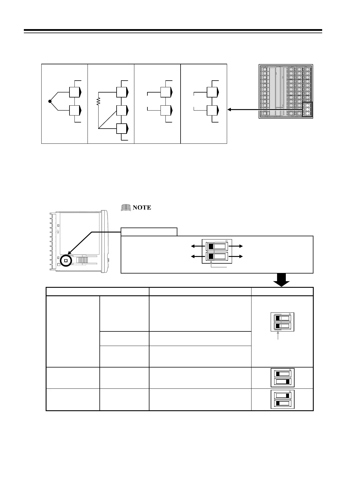
Measured input (TC/RTD/Voltage/Current) [universal input]
For the Measured input type, terminals 22 through 24 are allocated to the Measured input.
Select the Voltage (low) input group, the Voltage (high) input group or the Current input group to
conform to the input type to be set.
How to switch Input group:
Switch the input group by using the upper Input select switch at the bottom left of the left side of this
instrument. Select the voltage input or the current input by using the lower input select switch (refer to
the description below).
Input group Input type Input select switch
Voltage (low) input
group
TC input K, J, E, T, S, R, B, N (JIS-C1602-1995)
PLII (NBS)
W5Re/W26Re (ASTM-E988-96)
U, L (DIN43710-1985)
PR40-20 (ASTM-E1751-00)
RTD input Pt100 (JIS-C1604-1997)
JPt100 (JIS-C1604-1981 Pt100)
Voltage (low)
input
0 to 10 mV DC, 0 to 100 mV DC,
0 to 1 V DC, 10 to 10 mV DC,
100 to 100 mV DC, 1 to 1 V DC
Current input group Current input 0 to 20 mA DC, 4 to 20 mA DC
Voltage (high) input
group
Voltage (high)
input
0 to 5 V DC, 1 to 5 V DC, 0 to 10 V DC
5 to 5 V DC, 10 to 10 V DC
For TC input, use the appropriate compensation wire.
For RTD input, use low resistance lead wires with no difference in resistance between the three lead
wires.
To avoid noise induction, keep input signal wire away from instrument power line, load lines and
power lines of other electric equipment.
Input select switch
(Dip switch)
Side view
Voltage (high) input group
Input select switch
Input select switch (Dip switch)
Voltage (low) input group
Current input Voltage input
To avoid damage to the instrument, disconnect measurement
input terminals before switching input groups.
RTD inpu
TC input Voltage input
Current inpu
TC
24
23
RTD
A
B
B’
23
22
24
IN
24
23
IN
24
23

 Loading...


