4. BASIC OPERATION
IMR02L04-E3
4-12
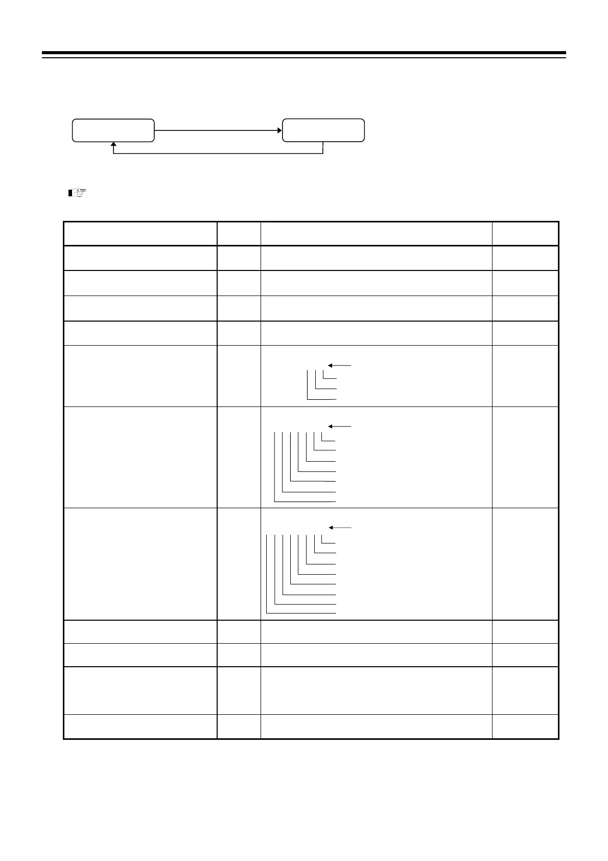
Monitor mode
The contents of the monitor display are same in any operation mode (RESET, RUN, FIX, MAN).
Refer to P. 4-13 to switch parameter setting display.
Parameter list
Name Symbol Data range
Factory set
value
Pattern remaining time monitor
PTN.TM
From 0:00 to 999:59 (Hour: Minute), or
from 0:00 to 999:59 (Minute: Second)
Segment repeat remaining time/
execution time monitor
1
RPT.SG
0 to 9999 times
Pattern repeat remaining time/
execution time monitor
1
RPT.PN
0 to 10000 times
10000: No limit
Total pattern remaining time/
execution time monitor
1
RPT.PR
0 to 10000 times
10000: No limit
Wait condition monitor
WAIT
Display: Not in wait state O Display: In wait state
OOO Value at SV display
Zone wait of the controller
Zone wait of the slave
Zone wait of the DI
Event state monitor
EV
Display: OFF O Display: ON
OOOOOOO Value at SV display
Event 1
Event 2
Event 3
Event 4
HBA1
HBA2
LBA
Time signal state monitor
TS
Display: OFF O Display: ON
OOOOOOOO Value at SV display
Time signal 1
Time signal 2
Time signal 3
Time signal 4
Time signal 5
Time signal 6
Time signal 7
Time signal 8
Current transformer 1 (CT1) input
value monitor
2
CT1
0.0 to 100.0 A
Current transformer 2 (CT2) input
value monitor
2
CT2
0.0 to 100.0 A
Manipulated output value 1 (MV1)
[heat-side] monitor
MV1
PID control, Heat/Cool PID control:
5.0 to 105.0 %
Position proportioning PID control:
0.0 to 100.0 % (Displays the
FBR input value)
Manipulated output value 2 (MV2)
[cool-side] monitor
3
MV2
5.0 to 105.0 %
1
Execution time monitor can be displayed by setting Repeat remaining process/program progression display at F10.12 in the Initial
level engineering mode. For Initial level engineering mode, refer to the PF900/PF901 Instruction manual (IMR02L03-E) on
the CD-ROM.
2
Displays only when CT input (optional) is specified. CT input value monitor displays CT input value as 1.1 times the average
current. CT input value is displayed for both Time proportional output and Current output. For Current output, the error of
measurement between actual current value and monitor display value becomes large when load factor is other than 0 % or 100 %.
3
Displayed when the Heat/Cool PID control is selected.
PV/SV monitor
Monitor mode
Press the
key
Press the
key to
switch monitor display.
Press the direct key (RUN, FIX, MAN or RESET) of the operation mode in
progress to go back to the PV/SV monitor display from monitor screens.

 Loading...


