3. WIRING
IMR02L04-E3
3-15
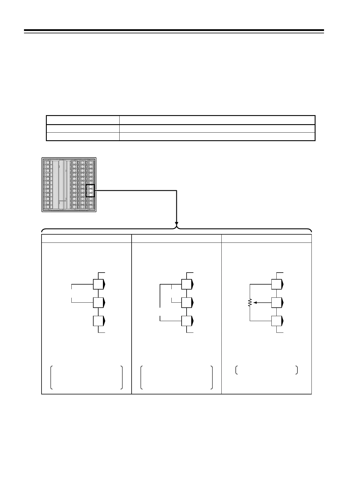
Current transformer (CT) input/Feedback resistance (FBR) input
[optional]
With CT input or FBR input, terminals 19 through 21 are allocated to the specified input.
When using CT input, connect CTs to the relevant terminals.
CT: CTL-6-P-N [input range 0 to 30 A] (sold separately)
CTL-12-S56-10L-N [input range 0 to 100 A] (sold separately)
When CT type is not specified at ordering, the factory set value of the CT ratio is “800.” To use
CTL-12-S56-10L-N, change the set value of CT ratio into “1000” at the setting screen described below.
CT input terminal Setting screen
CT1 Engineering mode F45.01: CT1 ratio (CTR1) [Refer to P. 4-40.]
CT2 Engineering mode F46.01: CT2 ratio (CTR2) [Refer to P. 4-40.]
When using FBR input, connect a potentiometer to the relevant terminals.
CT1/CT2/FBR (optional)
CT input (1 point)
Specification code: T
Quick start code 2 (Initial
setting code): P or S
CT input (2 points) FBR input
Allowance resistance:
Standard 135
(Availability: 100 to 10 k)
20
19
21
CT1
19
20
21
COM
CT1
CT2
19
20
21
O
W
C
O: OPEN
W: WIPE
C: CLOSE
Specification code: T
Quick start code 2 (Initial
setting code): T or U
Specification code: F

 Loading...


