3. WIRING
IMR02L04-E3
3-14
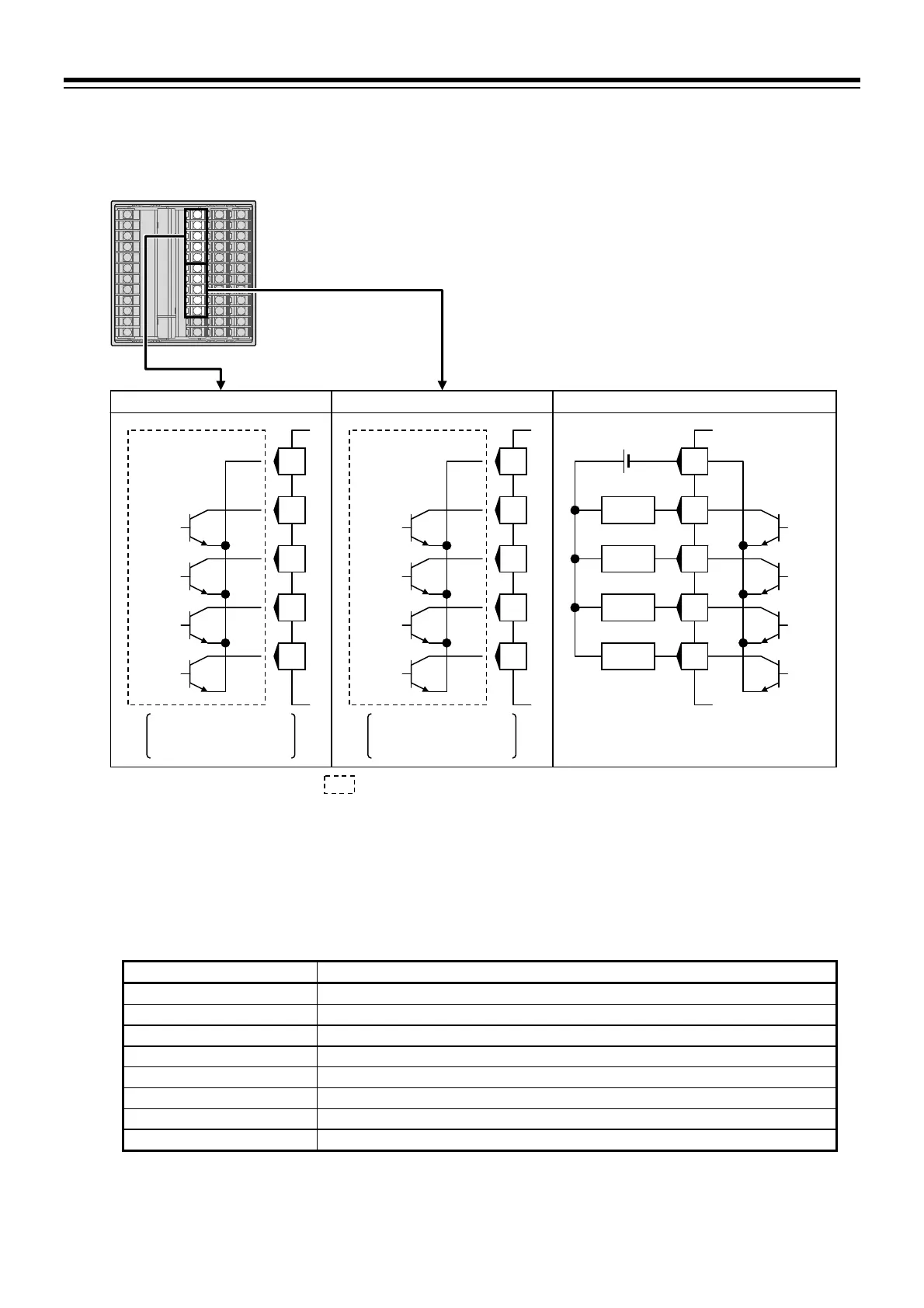
Digital output 5 to 12 (DO5 to DO12) [optional]
With DO optional, terminals 37 through 41 (DO5 to DO8) and 42 through 46 (DO9 to DO12) are
allocated to the DO.
Output type is only open collector output.
Output method: Sink type
Allowable load current: 100 mA
Load voltage: 30 V DC or less
ON voltage: 2 V or less (at maximum load current)
Leakage current at OFF: 0.1 mA or less
Assign Event type at the setting screen below.
Digital output terminal Setting screen
DO5 Engineering mode F34.05: DO5 assignment (Ldo5) [Refer to P. 4-38.]
DO6 Engineering mode F34.06: DO6 assignment (Ldo6) [Refer to P. 4-38.]
DO7 Engineering mode F34.07: DO7 assignment (Ldo7) [Refer to P. 4-38.]
DO8 Engineering mode F34.08: DO8 assignment (Ldo8) [Refer to P. 4-38.]
DO9 Engineering mode F34.09: DO9 assignment (Ldo9) [Refer to P. 4-38.]
DO10 Engineering mode F34.10: DO10 assignment (Ldo10) [Refer to P. 4-38.]
DO11 Engineering mode F34.11: DO11 assignment (Ldo11) [Refer to P. 4-38.]
DO12 Engineering mode F34.12: DO12 assignment (Ldo12) [Refer to P. 4-38.]
: The dotted box diagram describes the output state of the instrument.
DO9 to DO12 (optional)
DO5 to DO8 (optional)
COM ()
37
38
39
40
41
DO5
DO6
DO7
DO8
COM (
)
42
43
44
45
46
DO9
DO10
DO11
DO12
DO5 to DO8 DO9 to DO12 Wiring example
Specification code:
A or C
Specification code:
A or C
Load
COM ()
37
38
39
40
41
DO5
DO7
DO8
Load
Load
Load
DO6
+

 Loading...


