3. WIRING
IMR02L04-E3
3-2
Input/Output wiring
For thermocouple input, use the appropriate compensation wire.
For RTD input, use low resistance lead wire with no difference in resistance between the three lead
wires.
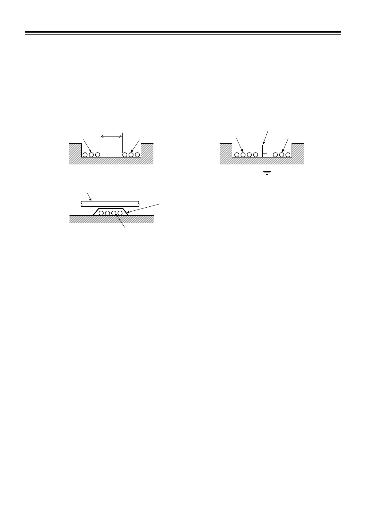
To avoid noise induction, keep input signal wire away from instrument power line, load lines and power
lines of other electric equipment.
Example: Keep 150 mm or more between Example: Locate separator.
the cables.
Example: Cross the cables at a right angle.
Use independent ducts for the input/output wires and power circuits inside and outside the panel.
Power supply cables
150 mm or more
Signal cables
Separator
Power supply cables
Ground
Signal cables
Signal cables
Power supply cables
Place materials such as the iron plate with a
thickness of 1.6 mm between the cables.

 Loading...


