IMR02L04-E3 7-1
7. ERROR DISPLAY
7.1 Display when Input Error Occurs
The table below shows displays, description, control actions and solutions when the Measured value (PV)
exceeds the display range.
Prior to replacing the sensor, always turn OFF the power.
Display
Description Action (Output) Solution
Measured
value (PV)
[Flashing]
Measured value (PV) exceeds the
Input scale high/low.
Measured value (PV) exceeds the
Input error determination point
(high/low limit).
Action at input error:
Output depending on
the Action (high or low) at
input error
(Refer to the PF900/PF901
Instruction Manual.)
Event output:
Output depending on the
Event output action at input
error
Check Input type, Input
range and connecting state
of sensor.
Confirm that the sensor or
wire is not broken.
ooooo
[Flashing]
Over-scale
Measured value (PV) is above the input
display range high (or +99999).
uuuuu
[Flashing]
Underscale
Measured value (PV) is below the input
display range low (or 19999).
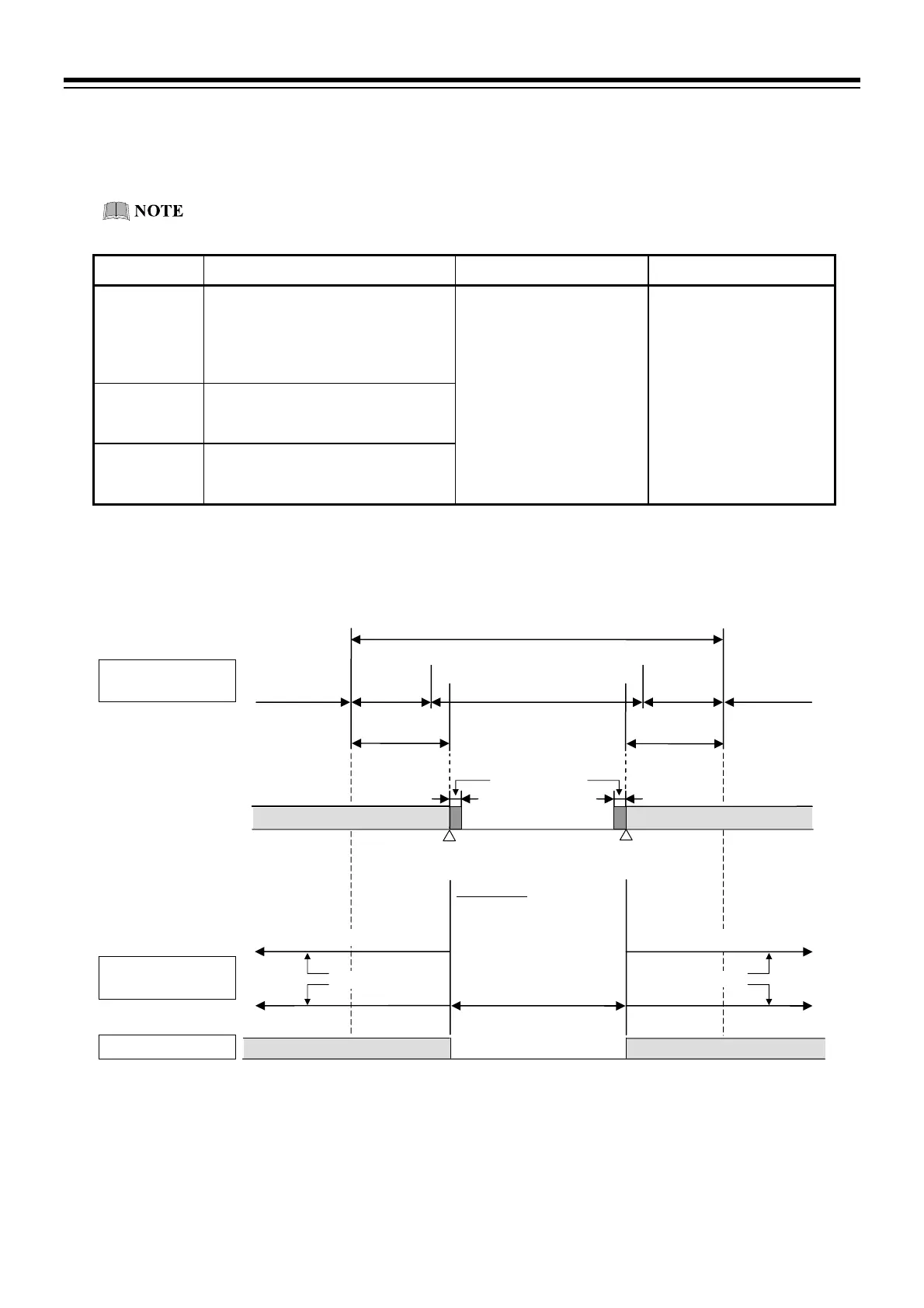
Setting Input error determination point within input range
Input range
(Input span)
Input display range
(Setting range of the input error determination point)
Measured value
(PV) display
Over-scale Underscale
5 % of
Input span
Input range low Input range high
Measured value
(PV) flashing
1
Action area at input error Action area at input error
Differential gap
(0.1 % of Input span)
Event
Input abnormality signal
Present output
Present output
Program control mode (RUN)
Manipulated output value (MV) of
the segment in progress
Fixed set point control mode (FIX)
Manipulated output value (MV)
Manual control mode (MAN)
Manipulated output value (MV) at
manual setting
Manipulated output
(MV)
Input error
determination point (low)
1
“Flashing display” or “Non-flashing display” of PV can be selected for the PV flashing display at input error of the Engineering mode
(F10.01).
2
For Event output at input error and Input abnormality output, refer to the PF900/PF901 Instruction Manual (IMR02L03-E) on the
CD-ROM.
Chooses eithe
Chooses either
Manipulated output at input erro
5 % of
Input span
Measured value
(PV) flashing
1
Input error
determination point (high)
Manipulated output at input error
Present output
Input abnormality signal

 Loading...


