7. ERROR DISPLAY
IMR02L04-E3
7-2
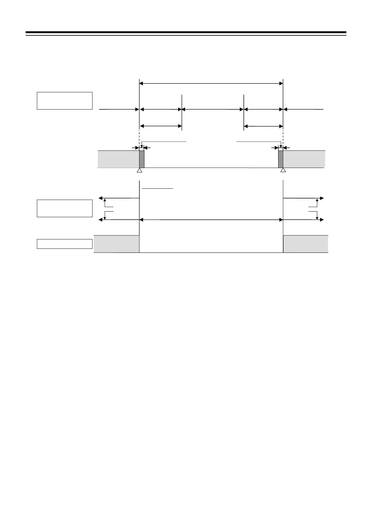
Setting Input error determination point when out of input range
Present output
Input range
(Input span)
Input display range
(
Setting range of the input error determination point)
Measured value
(PV) flashing
1
Manipulated output
at input error
5 % of
Input span
5 % of
Input span
Input range low
Input range high
Differential gap
0.1 % of Input span
Action area at
input error
Action area at
input error
Chooses
either
Input abnormality
signal
2
Input error determination point (low)
Input error determination point (high)
Present output
Program control mode (RUN): Manipulated output value (MV) of
the segment in progress
Fixed set point control mode (FIX): Manipulated output value (MV)
Manual control mode (MAN): Manipulated output value (MV) at
manual setting
Over-scale Underscale
Measured value
(PV) flashing
1
Manipulated output
at input error
Chooses
either
Present output
Input abnormality
signal
2
Measured value
(PV) display
Event
Manipulated output
(MV)
1
“Flashing display” or “Non-flashing display” of PV can be selected for the PV flashing display at input error of the Engineering mode
(F10.01).
2
For Event output at input error and Input abnormality output, refer to the PF900/PF901 Instruction Manual (IMR02L03-E) on the
CD-ROM.

 Loading...


