Rockwell Automation Publication 450L-UM001D-EN-P - December 2019 119
Status Indicators and Troubleshooting Chapter 7
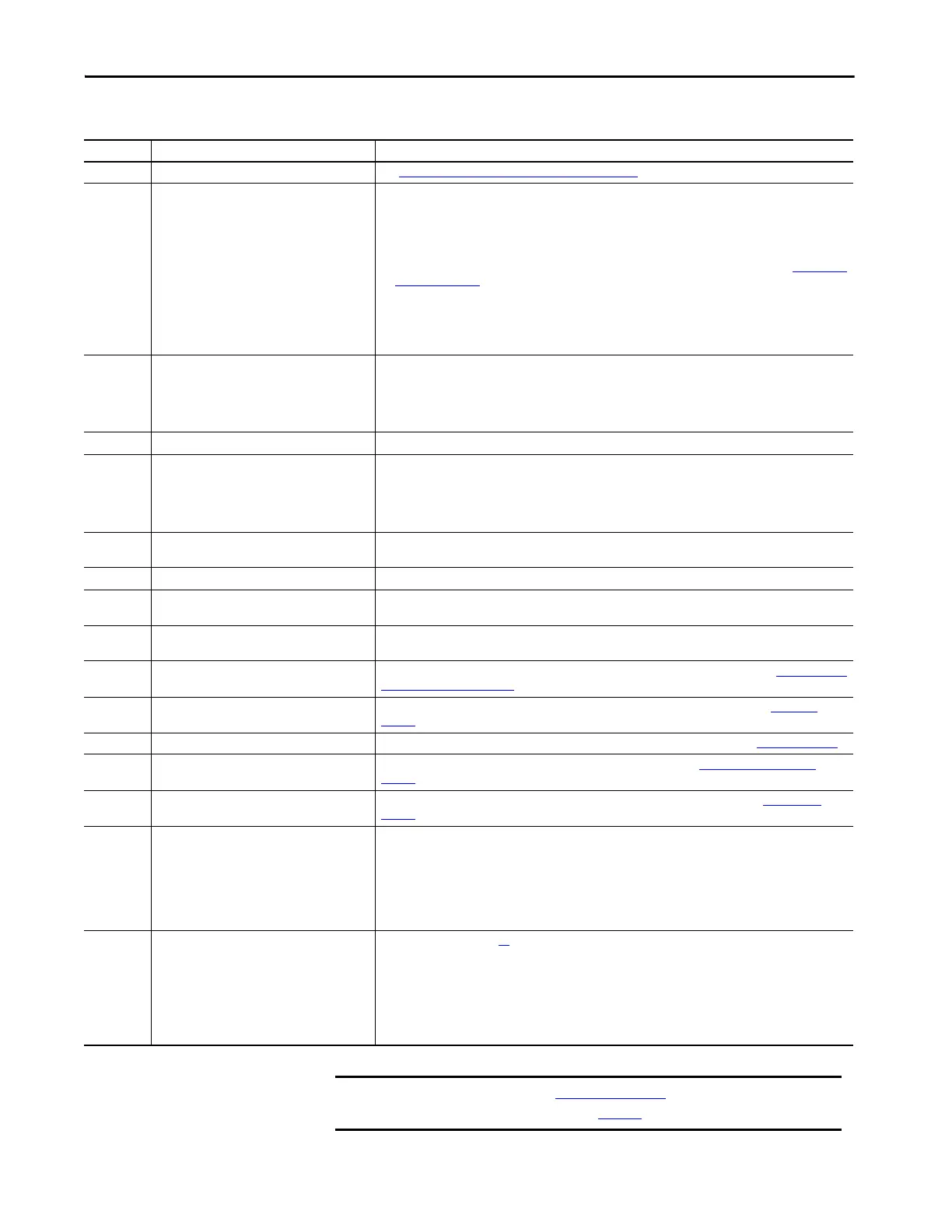
Table 55 - Errors, Lockouts, and Corrections
Condition Error Description Action
0 Confirmation changed See Confirmation of a New System Configuration on page 64
.
1 Internal lockout
Make sure that the correct plug-in is inserted and that the DIP switch settings of the plug-in are in correct
position.
One of the following methods clears the lockout mode of a transmitter stick:
1. Power down, then power up. If the fault is still present, the module lockout occurs again.
2. A reset signal longer than 10 seconds and less than 20 seconds acts like a power-up.
3. Press your finger on the optical push button longer than 10 seconds and less than 20 seconds (Optical Push
Button on page 116)
If the fault persists, replace the 450L-B safety light curtain transceiver stick.
Further diagnosis options are possible with the Connected Components Workbench in combination with the
USB/ optical interface device (OID; Cat No. 450L-AD-OID). If the 450L-B safety light curtain unit has a lockout,
the exact fault description can be determined with these tools.
2
EDM feedback signal at receiver plug-in not okay
(external error)
Short circuit between or to ground or over current at OSSDs
1. Check wiring and function of external contactor
2. Check connected relay for closed contact (if OSSD ON-input “Relay monitoring” must have GND level, if
OSSD OFF-input “Relay monitoring” must have +24V)
3. Repower the system or use adequate action after the lock out source is removed.
3 Start signal not okay Check signal status and signal timing at receiver plug-in for the manual start
4
Ambient light can lead to short sporadic switch
off the OSSD.
Check system set-up and remove foreign ambient light source. Ambient light sources can be:
• Strong flashing beacon
• Infrared remote controls
• Laser pointers
• Infrared light sensors
5
Short circuit between or to ground or over current
at OSSDs
Check wiring and connected components at the two OSSDs
6 Error supply voltage Check 24V DC power that is supplied to the stick
7
Voltage that is connected to transmitter plug-in
input
Make sure DIP switch 4 is set to the default position (off). Make sure that the 24V DC voltage is not supplied to
pin 4 of the 450L-APT-PW-5 part or voltage supply to pin 1 of the 450L-APT-PW-8 plug-in connector.
8
Stick identification mismatch when beam coding
is used
Check design according to chapter: Beam coding on page 30
9 Invalid DIP switch setting
Make sure that the DIP switch settings of the inserted plug-in refer to one that is described in Receiver Plug-in
DIP Switch Settings on page 60
10 Muting timing error (450L-E only)
Make sure that of the muting times are not above maximum or below minimum limits (see Muting on
page 38)
11 Muting sequence error (450L-E only) Make sure that the connected muting sensors are interrupted in the right sequence (see Muting on page 38
)
12 Blanking error (450L-E only)
Make sure that beams of fixed blanked objects are always interrupted (see Teach-in Fixed Blanking on
page 31)
13 Cascading error (450L-E only)
Make sure that the OSSDs of the connected safety component do not exhibit an error (see Cascading on
page 48).
14 System cannot be aligned
Make sure that both edges are parallel and installed at the same level.
Make sure that the transparent front cover is clean, no dust and is not scratched.
Make sure that the distance between transmitter and receiver is above the minimum distance.
Make sure that the distance between transmitter and receiver is below maximum distance.
Make sure that “low operation range” is not activated if operated above maximum range of the “low
operation range” function
15 OSSD outputs switch off sporadically
Check all hints of condition 14 first
Check that no ambient light from other sensors or sun or adjacent light curtain system can have an impact on
the performance of a GuardShield safety light curtain system.
Make sure that the power supply is adequate and the devices that are connected to the OSSD outputs are
within the limits.
Make sure that the GuardShield safety light curtain connection cables are not parallel to high-power supply
cables of the application
IMPORTANT Conditions 0…13 of Table 54 on page 118 show the status indicator for
condition numbers 0…13 in Table 55
.
 Loading...