Rockwell Automation Publication 450L-UM001D-EN-P - December 2019 85
Installation and Wiring Chapter 6
Two M6 DIN 912 screws (not provided) are required (minimum) for proper
mounting of each clamp.
Use additional side mounting brackets in vibration applications for protective
heights of 1050 mm (41.3 in.) and larger. Position and mount the additional
bracket in the middle of each stick.
Table 30 - Number of Side Mounting Brackets without Top/Bottom Brackets
Table 31 - Number of Side Mounting Brackets and Top/Bottom Brackets
The required screwdriver type for installation of the side mounting kit is a hex tip
screwdriver for M6 screws.
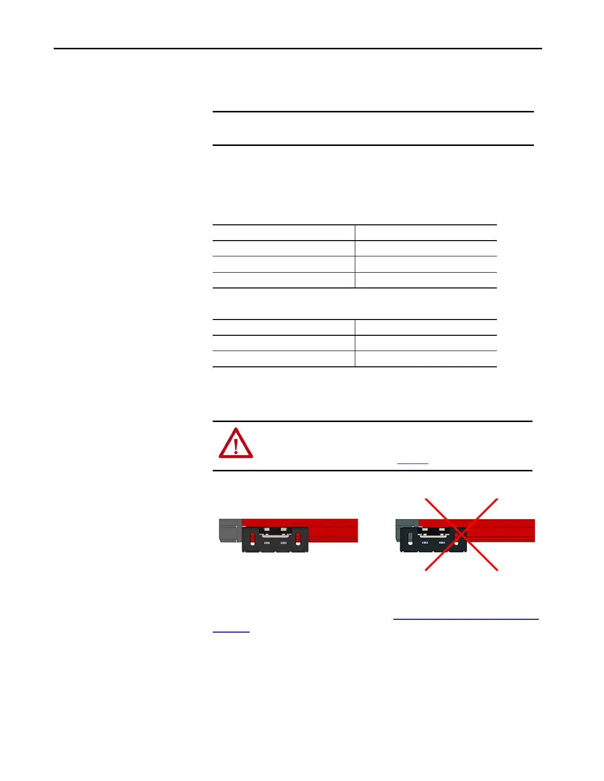
Figure 56 - Correct and Incorrect Positioning of the Side Mounting Bracket
Position the side mount brackets close to the gray end cap. Position additional
brackets so that the distance between each bracket is equal (symmetric). The
optical interface device 450L-AD-OID (see Optical Interface Device (OID) on
page 120) can also be installed in combination with the side mounting brackets.
IMPORTANT Use side mounting brackets and, or instead of, the top/bottom mounting
kits in vibration applications.
Stick Length Number of Side Mounting Brackets Per Stick
150 mm (5.9 in.) 1
300…900 mm (11.8…35.43 in.) 2
1050…1950 mm (41.34…76.77 in.) 2 (3 for vibration applications)
Stick Length Number of Side Mounting Brackets Per Stick
150…900 mm (5.9…35.43 in.) 0
1050…1950 mm (41.34…76.77 in.) 1 for vibration applications
ATTENTION: The light curtain can be damaged if the maximum torque
exceeds 11 N•m (97.36 lb•in).
Do not clamp the gray plastic end cap (Figure 56
).
 Loading...