Frame 3A and 3B Installation 3-5
PowerFlex® 700L Liquid-Cooled Drive User Manual
Publication 20L-UM001D-EN-P
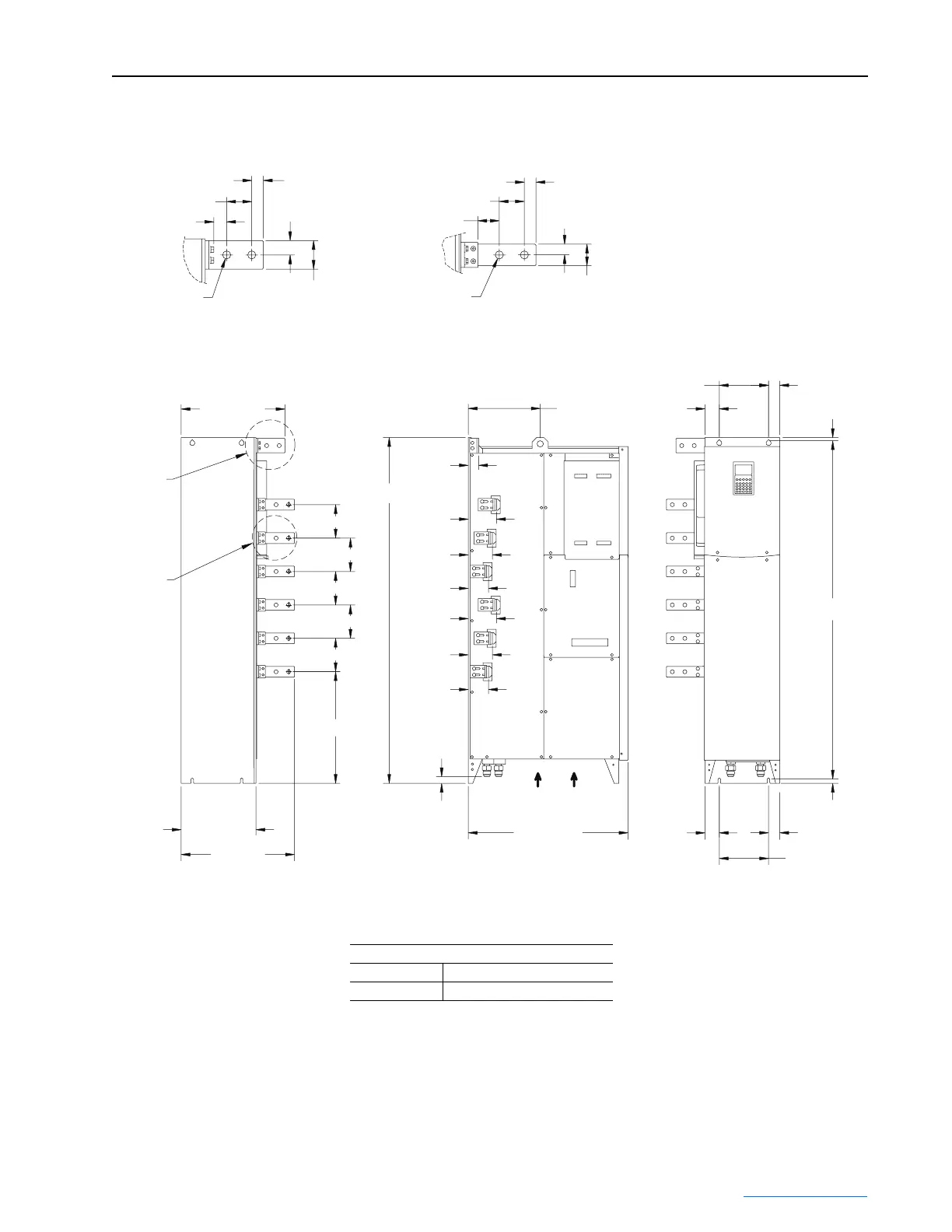
Figure 3.4 Frame 3A Converter/Inverter Power Module Installation Dimensions
44 (1.75)
23 (0.90)
DETAIL A
Ø
14 (
Ø
0.56)
21 (0.81)
25 (1.00)
51 (2.00)
44 (1.75)
21 (0.81)
38 (1.50)
19 (0.73)
38 (1.50)
DETAIL B
Ø
14 (
Ø
0.56)
Dimensions are in millimeters and (inches).
119 (4.67)
119 (4.67)
119 (4.67)
119 (4.67)
119 (4.67)
396 (15.59)
265 (10.44)
402 (15.82)
368 (14.50)
BACK VIEW
See
DETAIL B
See
DETAIL A
LEFT SIDE VIEW FRONT VIEW
37 (1.46)
100 (3.95)
86 (3.39)
72 (2.83)
72 (2.83)
24 (0.94)
567 (22.32)
51 (1.99)
15 (0.60)
1200 (47.25)
39 (1.56)
175 (6.89)
86 (3.39)
100 (3.95)
1227 (48.30)
255 (10.05)
175 (6.89) 39 (1.56)
12 (0.45)
51 (1.99)
AIRFLOW
GRD
R/L1
S/L2
T/L3
U/T1
V/T2
W/T3
Approximate Weight kg (lbs.)
Power Module Power Module and Packaging
112 (247) 144 (317)
 Loading...


