27—UTILITY Menu Parameters
354 www.RolandUS.com Roland VS-2400CD Owner’s Manual
SYSTEM
PHANTOM SW
The VS-2400CD provides phantom power for its eight XLR inputs, as described on
Page 126. Each input’s phantom power on/off switch is available in two places, on the
EZ ROUTING PATCH BAY screen—described on Page 126—and on the SYSTEM
Param1 screen. Setting an input’s ANALOG INPUT switch on the SYSTEM Param1
screen is the same as setting its PATCH BAY screen PHANTOM POWER on/off switch.
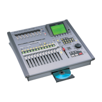
EXT LEVEL METER (MB-24)
Use these parameters to set the behavior of the MB-24 meter bridge (purchased
separately) attached to your VS-2400CD. If you’re not using an MB-24, you can ignore
these parameters.
DISPLAY SECTION
The DISPLAY SECTION parameter selects the type of signals shown in the MB-24’s 24
SECTION level meters. They can be turned off, or set to show:
You can jump instantly to the PATCH BAY screen’s PHANTOM POWER settings by
holding down SHIFT and pressing EZ ROUTING•PHANTOM.
To learn how to connect an MB-24, see “Connecting an MB-24 Level Meter” on
Page 377.
MB-24 cannot be attached VS-2400CD unit itself. MB-24 should be installed in your
system rack with the rack mount adaptors included in its package.
For details refer to MB-24 Owner’s Manual “Connecting the mixing processor
(VM-7100/VM-7200) and the MB-24” (Page 11, step 1).
Parameter Value: Meters show:
ANALOG INPUT 1-8 the levels received at the VS-2400CD’s analog inputs
R-BUS/COAX/OPT IN the levels received at the R-BUS, coaxial and optical digital
inputs
INPUT MIXER 1-16 input channel levels
TRACK MIXER 1-24 track channel levels
FX1-4 RETURN effect processor output levels
AUX1-8/DIR1-8 Aux bus and Direct path levels
ANALOG OUTPUT analog output jack levels
R-BUS/COAX/OPT OUT R-BUS, coaxial and optical digital output levels
The “Supplemental Information” chapter provides further information regarding the
MB-24. See “Roland MB-24 Notes” on Page 452.
UTILITY menu
F1 (SYSTEM)
VS2400OMUS.book 354 ページ 2006年2月28日 火曜日 午前11時12分
 Loading...