S3F84B8_UM_REV 1.00 6 INSTRUCTION SET
6-51
6.3.38 LDC/LDE — LOAD MEMORY
LDC/LDE dst,src
Operation: dst src
This instruction loads a byte from program or data memory into a working register, or vice versa.
The source values remain unaffected. LDC refers to program memory, while LDE refers to data
memory. The assembler makes ‘Irr’ or ‘rr’ values even for program memory and odd for data
memory.
Flags: No flags are affected.
Format:
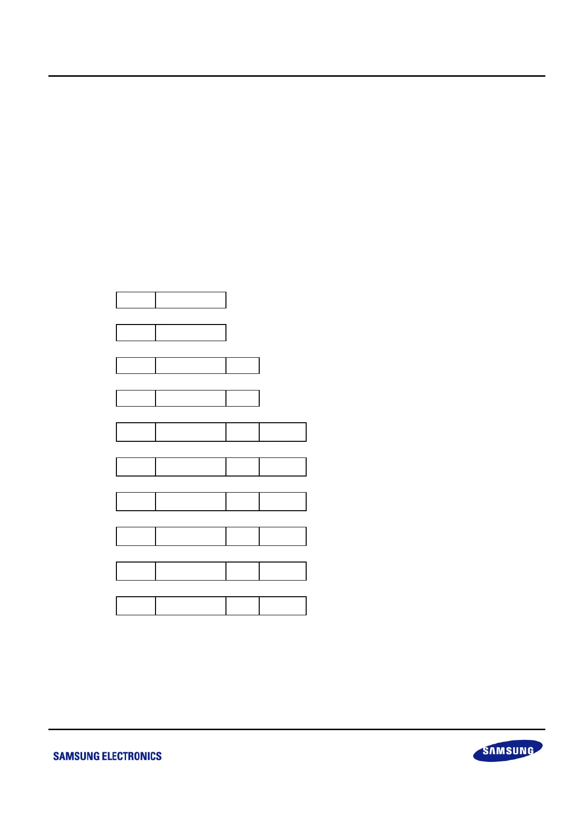
Bytes Cycles Opcode
(Hex)
Addr Mode
dst src
1. opc dst | src 2 10 C3 r Irr
2. opc src | dst 2 10 D3 Irr r
3. opc dst | src XS 3 12 E7 r XS [rr]
4. opc src | dst XS 3 12 F7 XS [rr] r
5. opc dst | src
XL
L
XL
H
4 14 A7 r XL [rr]
6. opc src | dst
XL
L
XL
H
4 14 B7 XL [rr] r
7. opc dst | 0000
DA
L
DA
H
4 14 A7 r DA
8. opc src | 0000
DA
L
DA
H
4 14 B7 DA r
9. opc dst | 0001
DA
L
DA
H
4 14 A7 r DA
10. opc src | 0001
DA
L
DA
H
4 14 B7 DA r
NOTE:
1. The source (src) or working register pair [rr] for formats 5 and 6 cannot use register pair 0–1.
2. For formats 3 and 4, the destination addresses ‘XS [rr]’ and source address ‘XS [rr]’ are one byte each.
3. For formats 5 and 6, the destination address ‘XL [rr] and source address ‘XL [rr]’ are two bytes each.
4. The DA and r source values for formats 7 and 8 address the program memory; the second set of values used in formats 9
and 10 address the data memory.



 To Next Page