S3F84B8_UM_REV 1.00 4 CONTROL REGISTERS
4-32
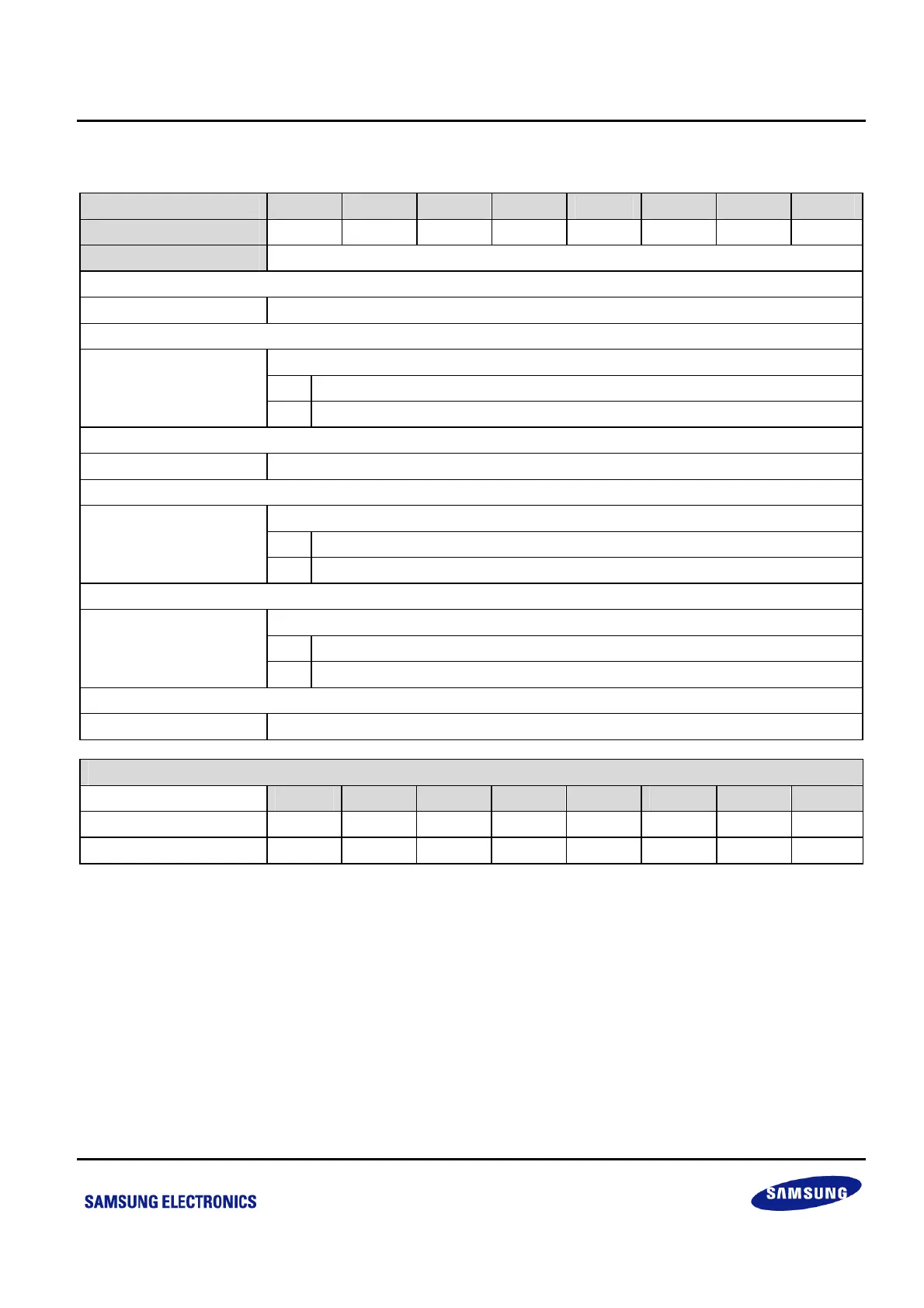
4.1.33 RESETID — RESET SOURCE INDICATING REGISTER: F2H, BANK1
Bit Identifier .7 .6 .5 .4 .3 .2 .1 .0
Read/Write
– – – R/W – R/W R/W –
Addressing Mode
Register addressing mode only
.7–.5 Not used for S3F84B8.
nReset Pin Indicating Bit
0 Reset is not generated by nReset pin (when read).
.4
1 Reset is generated by nReset pin (when read).
.3 Not used for S3F84B8.
WDT Reset Indicating Bit
0 Reset is not generated by WDT (when read).
.2
1 Reset is generated by WDT (when read).
LVR Reset Indicating Bit
0 Reset is not generated by LVR (when read).
.1
1 Reset is generated by LVR (when read).
.0 Not used for S3F84B8.
State of RESETID depends on the Reset Source
.7 .6 .5 .4 .3 .2 .1 .0
LVR – – – 0 – 0 1 –
WDT, or nReset pin – – –
(4)
–
(4) (3)
–
NOTE:
1. When LVR is disabled (Smart Option 3FH.7 = 0), RESETID.1 is invalid; when P0.2 is set as IO (Smart Option 3FH.2 = 0),
RESETID.4 is invalid.
2. To clear an indicating register, write “0” to indicating flag bit (writing “1” to reset indicating bits has no effect).
3. Once a LVR reset happens, RESETID.1 will be set and all the other bits will be cleared to “0” at the same time.
4. Once a WDT or nRESET pin reset happens, corresponding bit will be set, but leave all other indicating bits as unchanged.