S3F84B8_UM_REV 1.00 21 ELECTRICAL DATA
21-8
Table 21-6 Data Retention Supply Voltage in Stop Mode
(T
A
= –40C to + 85C, V
DD
= 1.8V to 5.5V)
Parameter Symbol Conditions Minimum Typical Maximum Unit
Data retention
supply voltage
V
DDDR
Stop mode 1.0 – 5.5 V
Data retention
supply current
I
DDDR
Stop mode; V
DDDR
= 1.8V
– – 1 uA
NOTE: Supply current does not include the current drawn through internal pull-up resistors or external output current
loads.
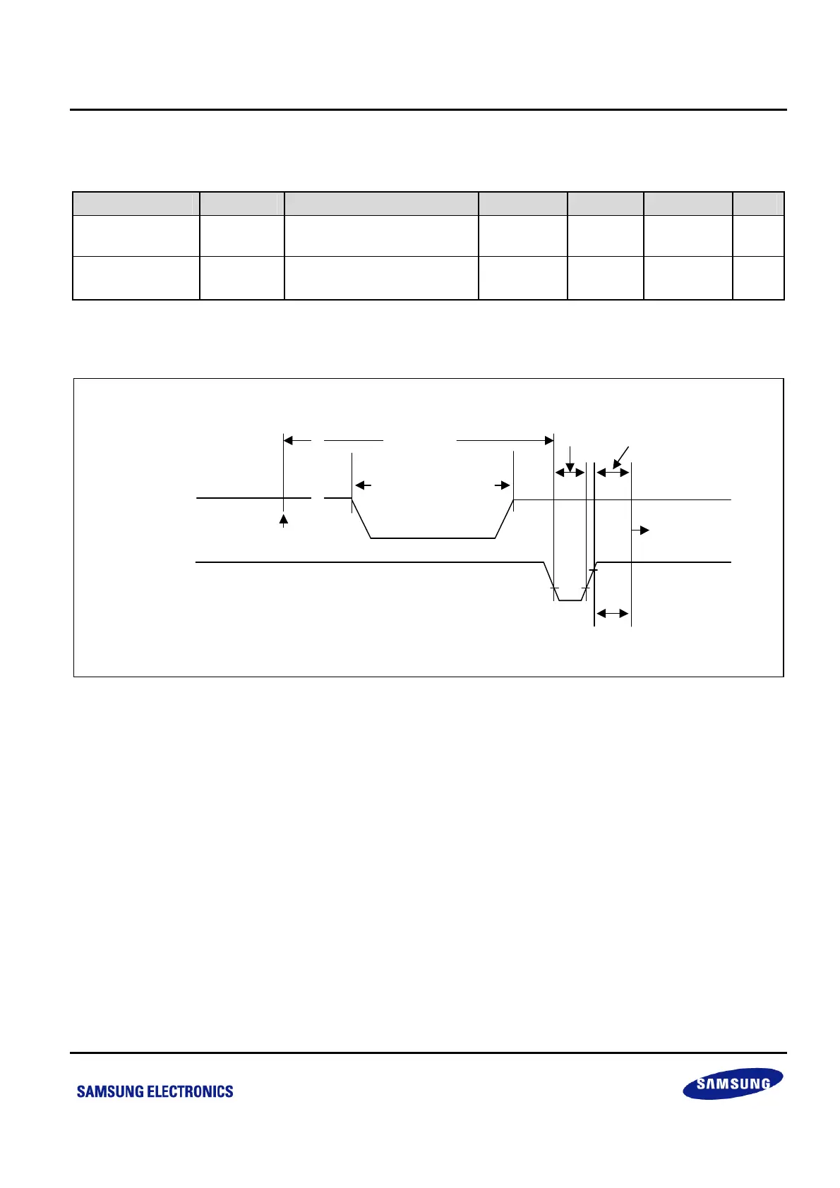
Data Retention
Mode
VDDDR
Execution Of
Stop Instrction
V
DD
Normal
Operating
Mode
Oscillator
Stabilization
Wait time
Stop
Mode
tWAIT
RESET
RESET
Occurs
NOTE: tWAIT
is the same as 4096 x 128 x 1/f
OSC
~
~
~
~
Figure 21-4 Stop Mode Release Timing When Initiated by a RESET
 Loading...